
Model Reconstruction
After creating a model, click Start to load the data. When data loading is complete, the My Models list page opens. In the relevant project in the model list, click Start Reconstruction, then click Confirm in the prompt to start automatic model generation.
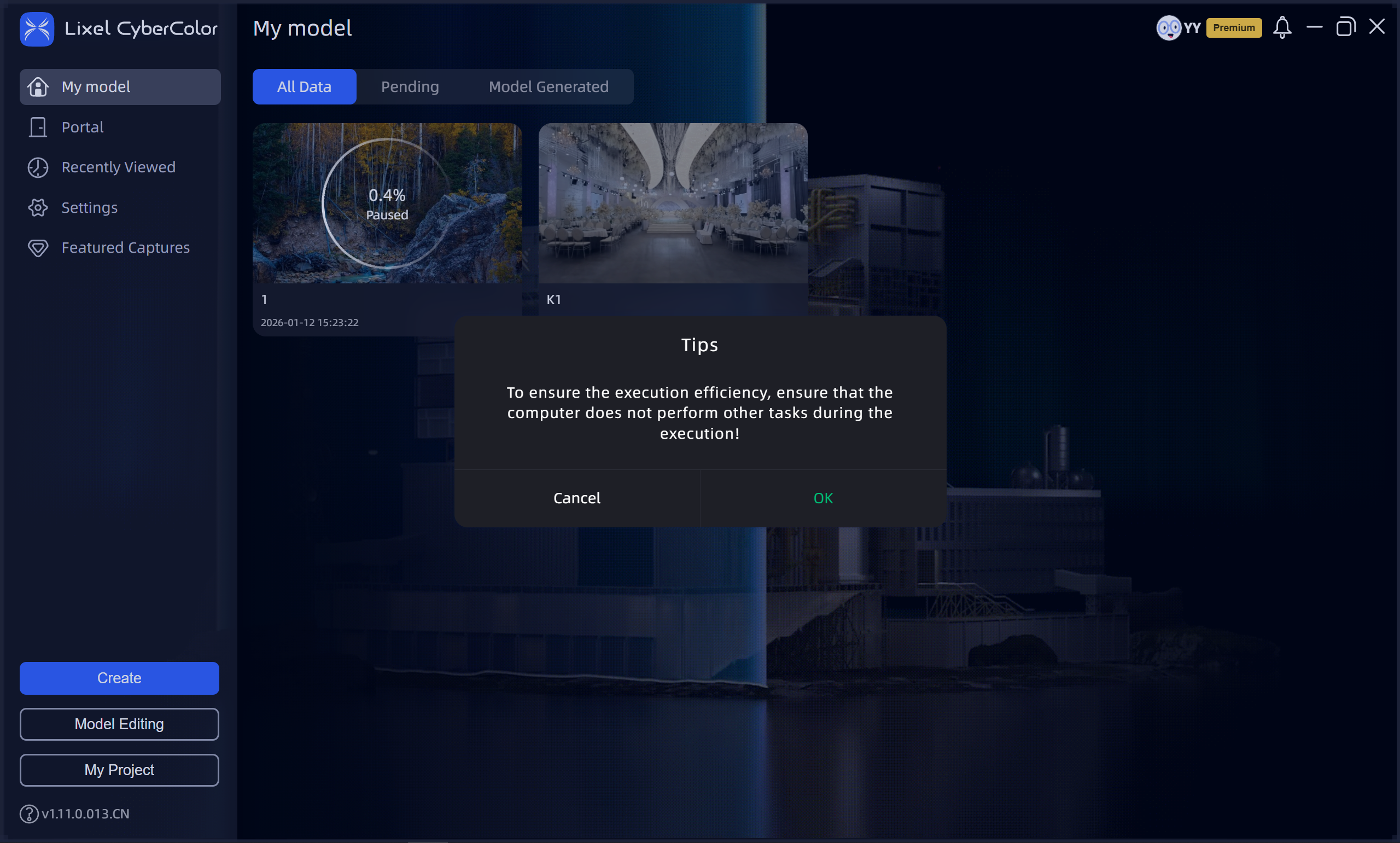
Start Reconstruction
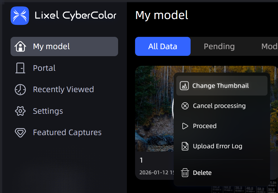
Reconstruction model card
Notes:
- When performing batch reconstruction tasks, make sure that all data to be processed has been uploaded before queuing it for reconstruction. To avoid reconstruction failures, do not run other tasks that may consume VRAM during reconstruction.
- Do not close LCC Studio during reconstruction, or the reconstruction task will be interrupted.
- When uploading captured data, make sure there is sufficient disk space in the directory where LCC data is stored. It is recommended that you reserve disk space at least twice the size of the capture project data to prevent reconstruction from being interrupted or failing due to insufficient space.
- Closing LCC Studio while the model is being generated interrupts generation. When you reopen LCC Studio, the model displays a reconstruction failure and the previous reconstruction progress. Click the upper-right corner of the model card, then click Continue Generation or Restart Generation to re-enter the model-generation queue.
Reconstruction Parameter Descriptions
Reconstruction Efficiency
Different efficiency options (Fast, Standard, and Slow) generate models with different signal-to-noise ratios. Slow reconstruction significantly increases VRAM consumption. Although this extends model-generation time, it ultimately produces higher-quality model results.
Maximum Gaussian Points
In Single Model Reconstruction mode, Maximum Gaussian Points directly limits the overall point count of the final reconstruction result. Therefore, keep it within the capacity of available VRAM (typically no more than 25M). Setting it too high may cause insufficient VRAM or reduced reconstruction performance, affecting the quality and stability of the final model.
In Map Fusion, Aerial-Ground Fusion, and Aerial Reconstruction modes, Maximum Gaussian Points applies only to the reconstruction scale of an individual block and does not limit the total number of Gaussian points in the final complete model. The system automatically adjusts the reconstruction range of each block according to model size. Therefore, setting Maximum Gaussian Points above 25M will not significantly affect the final overall reconstruction result.
Cross-Platform Optimization
Helps you generate LCC models that can be loaded on most devices. When optimization is enabled, LCC models are smaller and run more smoothly, meeting most model requirements and especially improving mobile rendering quality. When optimization is disabled, more realistic lighting and shadow effects can be achieved, but performance may decline or stuttering may occur.
Debug Options
Debug Options are a set of advanced configuration parameters for advanced users or developers. They are used to fine-tune the 3D reconstruction process, diagnose abnormal issues, or address accuracy and compatibility requirements in specific model scenarios.
Exposure Optimization:
Specifically optimizes floating artifacts in scenes with dramatic lighting changes, such as indoor-to-outdoor transitions, but may slightly degrade details in bright and dark areas. Enable it only when you encounter this type of issue.
PPR (Point Cloud Participation):
If sky adhesion occurs, such as at tree or building edges, try reconstructing again with a lower PPR.
Note: Adhesion is usually caused by capturing from a single viewpoint. For the best results, capture from additional angles and heights.
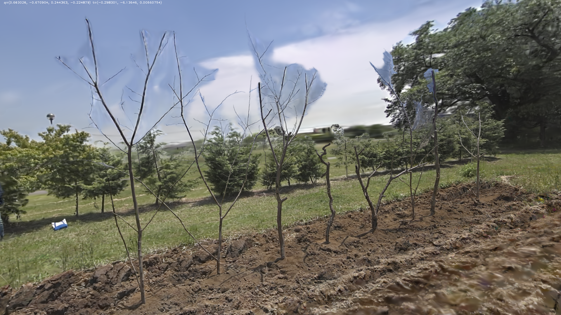
Before reduction (Normal)
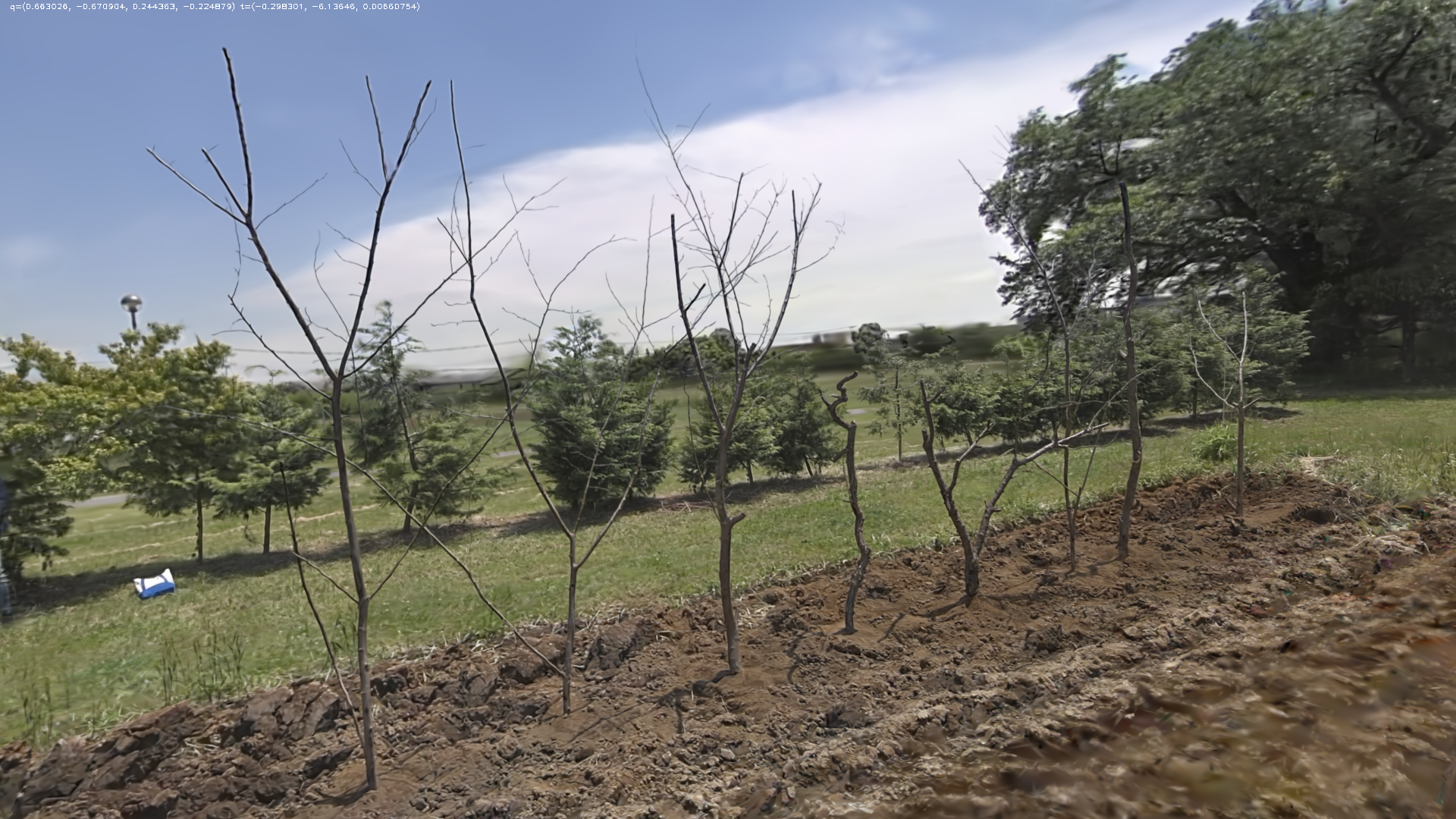
After reduction (Low)
RTK Data:
⚠️ Starting with v2.0.0, this option has been replaced by the Coordinate System Conversion feature. The RTK Data toggle is no longer available in Debug Options. For details, see the Coordinate System Conversion section below.
v1.x version notes (click to expand)
Controls whether RTK data recorded during scanning is used during reconstruction:
- Auto: The system prioritizes using RTK data. If it detects abnormal data, it automatically does not use the data, ensuring stable and reliable reconstruction results.
- Disable: Completely ignores RTK data. The result will not contain absolute coordinate information and cannot be used for Map Fusion or aerial-ground alignment, but it avoids issues caused by abnormal RTK data.
SLAM Special Mode:
You can select a SLAM mode that matches the usage environment for better reconstruction results:
- Auto (Recommended): Intelligently matches the best reconstruction strategy. It first attempts high-precision mode. If it detects failure caused by jitter or interference, it automatically switches to Robust Mode and retries, ensuring reconstruction success. Suitable for most scenarios.
- None: Prioritizes high modeling accuracy and is suitable for stable equipment and clear environments. Reconstruction may fail if there is jitter or interference during capture.
- Robust Mode (Default): Suitable for most scenarios. It balances accuracy and stability and provides a certain degree of interference resistance during capture.
- Narrow Scene: Specifically optimized for narrow environments such as tunnels, mine tunnels, and long corridors. Using it in ordinary scenarios may cause failure.
Point Cloud Preview Before Reconstruction
After uploading captured data and before starting a reconstruction task, you can use the Point Cloud Preview tool to view the capture trajectory and point cloud.
Steps: Upload captured data - Click Point Cloud Preview.
The system checks each metric one by one. You can adjust the captured data according to the results before reconstruction to improve reconstruction success and quality.
After the check is complete, click View Point Cloud to open the Point Cloud Preview tool page and view the capture trajectory and coarse-scan point cloud.
Operations in the Point Cloud Preview tool are the same as in LCC Scene Editor.
Coordinate System Conversion
When your scan data contains RTK positioning information, you can configure coordinate system conversion in the Reconstruction Parameters panel to output the reconstructed model directly in the target coordinate system, making it convenient to overlay with GIS/BIM data.
This feature replaces the legacy RTK Data debug option. The legacy version required you to manually determine whether RTK was available and select Auto or Disable. In the new version, the system makes this determination automatically—if RTK data is available, the system automatically completes coordinate conversion; if RTK data is unavailable or abnormal, the system automatically skips coordinate conversion and outputs the model normally, without affecting the reconstruction result. You only need to select the target coordinate system.
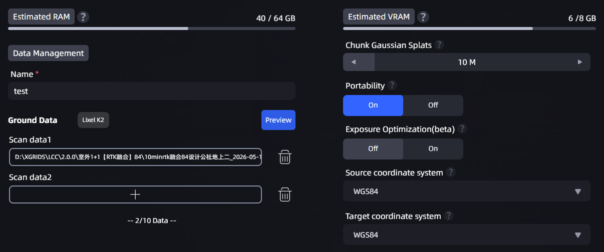
Location of the Coordinate System Conversion dropdown in the Reconstruction Parameters panel
Configuration Method
- In the Reconstruction Parameters panel, find the Source Coordinate System and Target Coordinate System dropdowns.
- The source coordinate system is automatically identified from your scan data (it defaults to WGS84 when RTK is available).
- Select the required coordinate system in the Target Coordinate System dropdown.
- Click Start Reconstruction. After reconstruction is complete, the point cloud is automatically converted to the selected coordinate system.
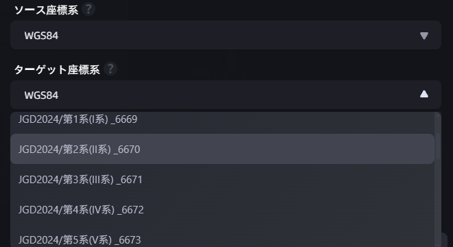
Expanded Target Coordinate System dropdown
Available Coordinate Systems
The available coordinate system options differ based on the software language setting:
| Software Language | Available Target Coordinate Systems |
|---|---|
| Simplified Chinese | None · WGS84 · CGCS2000 |
| Japanese | None · WGS84 · Japan Coordinate System (including 19 zones) |
| English | None · WGS84 |
- Selecting None performs no coordinate conversion and outputs the local coordinate system (the default behavior).
- Selecting another coordinate system requires scan data that contains RTK positioning information.
Exception Handling Logic
| Scenario | System Behavior |
|---|---|
| RTK data is normal | Coordinate conversion is completed automatically, and the model contains absolute coordinate information. |
| RTK data is abnormal (signal loss/insufficient accuracy/false fix) | Coordinate conversion is automatically skipped. The model is generated normally but does not contain absolute coordinates. |
| No RTK data (such as indoor capture) | The coordinate system option automatically displays None and cannot be changed. The model is generated normally. |
Note: If scan data does not contain RTK information, the coordinate system option displays None and cannot be changed. When selecting the Japan Coordinate System, you must further select a specific zone (1–19).
Layering Optimization
A Layering Optimization toggle has been added to the Advanced Tuning collapsible panel and is enabled by default. This feature applies only to scan data from PortalCam devices; on other devices, the toggle is grayed out and unavailable.
Feature Description
“Layering” refers to visual anomalies in a reconstructed model, such as misalignment, ghosting, or structural breaks (for example, the same wall appearing as two layers, or the floor and ceiling being offset). These issues usually occur when capturing along a large circular path and are caused by accumulated positioning deviation.
Layering Optimization corrects accumulated deviation through loop-closure detection. When you scan along a large loop path—such as circling a corridor, moving up and down multiple floors, or passing through the same area multiple times in a large scene—enabling this feature can significantly reduce model misalignment and ghosting.
When to Enable (Default)
- Scenes involving large loops (circling a long corridor, multiple floors, or passing through the same area multiple times in a large scene)
When to Disable
- Scenes containing multiple areas with highly similar textures or layouts (such as cubicles, repeated floors, symmetrical corridors, or chain stores)
Note: In scenes with similar textures, Layering Optimization may incorrectly identify different locations as the same location, causing structural distortion in the model. If the reconstruction result is abnormal, try disabling this toggle and reconstructing again.
Creator Data and NVIDIA nCore Data
Creator Data and NVIDIA nCore Data are for users who need to access data from the 3DGS reconstruction process.
Example Output Directory Structure
After reconstruction is complete, the two data directories are located under output/ in the model output directory. The following is a concise example of the actual output structure. Names and quantities such as map_0, camera_0, and camera_1 vary based on data captured by the hardware device. The following is an example of Creator Data produced by L2 Pro:
output/
├─ developer_data/
│  ├─ perspective/
│  │  ├─ images/map_0/{camera_0, camera_1}/
│  │  ├─ masks/map_0/{camera_0, camera_1}/
│  │  └─ sparse/
│  └─ raw/
│     ├─ images/map_0/{camera_0, camera_1}/
│     ├─ masks/map_0/{camera_0, camera_1}/
│     └─ sparse/
└─ nCore_data/
   ├─ colmap/
   │  ├─ perspective/
   │  │  ├─ images/map_0/{camera_0, camera_1}/
   │  │  ├─ masks/map_0/{camera_0, camera_1}/
   │  │  └─ sparse/0/
   │  └─ raw/
   │     ├─ images/map_0/{camera_0, camera_1}/
   │     ├─ masks/map_0/camera_0/
   │     └─ sparse/0/
   ├─ lidar/
   ├─ ncore4/
   └─ trajectory/
Enable Creator Data
Creator Data is intended for industry application developers, universities, integrators, and downstream rendering or simulation platforms that require complete processing capabilities and data outputs. Both the online and offline LCC Studio packages that support Creator Data can use this feature. Creator Data is free to use in the international version of LCC Studio; no authorization code or separate entitlement is required.
- Open Settings > Advanced.
- Enable Creator Data.
- After reconstruction is complete, view the generated data in
output/developer_data/in the model output directory.
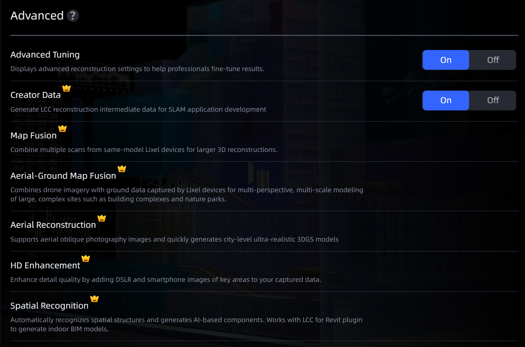
Creator Data settings
Data Overview
Creator Data includes raw image data and 3DGS intermediate-result data:
| Data Type | Description | Relative Path (output/developer_data/) |
|---|---|---|
| Original Images | Original fisheye images captured by XGIRDS devices | raw/images/ |
| Invalid Mask (Original Images) | Masks marking the locations of people and devices | raw/masks/ |
| Camera Extrinsic and Intrinsic Parameters (Original Images) | COLMAP-format intrinsics and extrinsics aligned with the LAS point cloud | raw/sparse/ |
| Undistorted Images | Undistorted perspective images | perspective/images/ |
| Invalid Mask (Undistorted Images) | Masks marking the locations of people and devices | perspective/masks/ |
| Camera Extrinsic and Intrinsic Parameters (Undistorted Images) | COLMAP-format intrinsics and extrinsics aligned with the LAS point cloud | perspective/sparse/ |
| Optimized Laser Point Cloud | Post-processed LAS point cloud | map_remov.las |
| Device Poses | Device poses in the IMU coordinate system (10 Hz) | poses.csv |
| High Frequency Device Poses | Device poses at the original frequency (200 Hz) | high_frequency_poses.csv |
Note: Raw image data does not include calibration files, meaning the relative extrinsic parameters between different sensors.
Original Images, Masks, and Camera Parameters
raw/images/ outputs original fisheye images and front-facing camera images (if available) captured by L2P, K2, K1, PortalCam, and other devices, along with corresponding people and device masks and camera intrinsic and extrinsic parameter data. Images have a resolution of 4000 × 3000 and use the .jpg format.
The output frame rate of original images is adjusted according to the Quality option during reconstruction: selecting Fast, Standard, or Slow outputs images at 1 Hz, 2 Hz, or 3 Hz, respectively. Masks in raw/masks/ semantically mark image pixels. In these masks, white areas indicate regions unsuitable for reconstruction, such as people and capture equipment.
raw/sparse/ provides COLMAP-format visual mapping results aligned with the LAS point cloud, including camera intrinsics and extrinsics for each image. You can use these data to:
- Develop customized visual mapping algorithms;
- Further optimize existing visual mapping results;
- Perform customized image undistortion according to business requirements.
Undistorted Images, Masks, and Camera Parameters
perspective/images/ contains ideal perspective images derived from raw fisheye images according to the panoramic image output frequency. The corresponding masks and COLMAP-format intrinsics and extrinsics are located in perspective/masks/ and perspective/sparse/, respectively.
Each fisheye image is split into three perspective images. Each perspective image has a horizontal field of view of 60° and a vertical field of view of 90°. Two fisheye images captured at the same time produce six perspective images, covering a panoramic range of 360° horizontally and 90° vertically. This data set is suitable for 3DGS, MVS, and other algorithms that require ideal perspective-image input.
Optimized LiDAR Point Cloud and Device Poses
map_remov.las is a LAS point cloud processed through global optimization and dynamic-point filtering. poses.csv provides 10 Hz device poses in the Lixel IMU coordinate system, and high_frequency_poses.csv provides 200 Hz high-frequency device poses at the original IMU frequency. These data can be combined with raw or undistorted images for visual and LiDAR post-processing reconstruction.
The coordinate alignment rules are as follows:
- Without RTK: LAS point cloud coordinates and the extrinsics of raw and undistorted images are in the same coordinate system.
- With RTK: After the LAS point cloud coordinates are corrected using the offset in the LAS file header, they are in the same coordinate system as the extrinsics of raw and undistorted images.
Both pose files use the following field format:
timestamp, tx, ty, tz, qw, qx, qy, qz
timestamp: Time, in seconds.tx,ty,tz: Translation from the IMU to the world coordinate system, in meters.qw,qx,qy,qz: Unitless rotation quaternion from the IMU to the world coordinate system.
Generate NVIDIA nCore Data
When creating a model, select NVIDIA nCore Data. After reconstruction is complete, you can view the developer_data folder and NVIDIA nCore Data in the output directory.
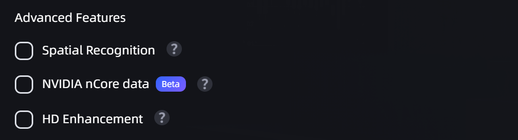
NVIDIA nCore Data