
Acquire Point Cloud Data with Absolute Coordinate
There are two ways to obtain absolute-coordinate point clouds: through external ground control points, or through the RTK module. The former suits a wide range of indoor and outdoor scenes; the latter requires a good outdoor RTK signal.
Through Ground Control Points
Overview
Collecting ground control points lets you:
- Convert the scanned point cloud into an absolute coordinate system.
- Optimize point cloud accuracy.
Control point layout requirements
- Minimum: at least 3 control points per scan, reasonably distributed and not too clustered.
- Quantity: determined by the project's accuracy requirements; in high-accuracy scenarios, more control points yield higher conversion accuracy.
- Distribution: control points should be evenly distributed across the survey area; the more even the distribution, the better the conversion.
Note
The number and distribution of control points directly affect coordinate conversion quality and point cloud accuracy. Plan the layout according to your project requirements.
Scanner Installation
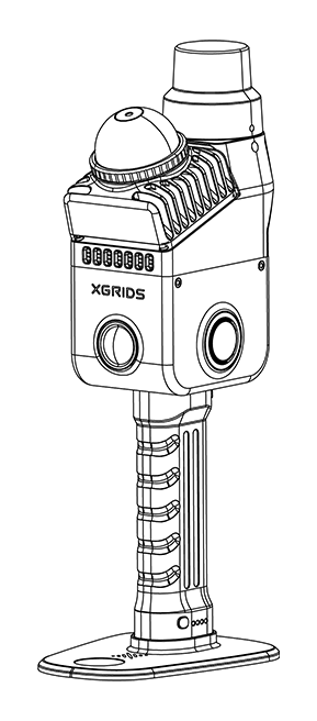
The components used include the Lixel K2 handheld scanner, battery, and control point base.
Field Work: Scanning
1. Field Survey and Planning
Control point design
- With a topographic map: design control point locations from the map and confirm/adjust during the on-site survey.
- Without a topographic map: design directly based on the on-site environment.
Control point layout requirements
| Item | Requirement |
|---|---|
| Distribution | Control points should be evenly distributed across the survey area |
| Spacing | Keep adjacent control points within 50 m |
| Quantity | At least 3 control points |
Note
Control points must not be arranged in a straight line.
2. Start Scanning
Turn on the scanner and start scanning via LixelGO or the device button (see Scanning Workflow).
Capture steps
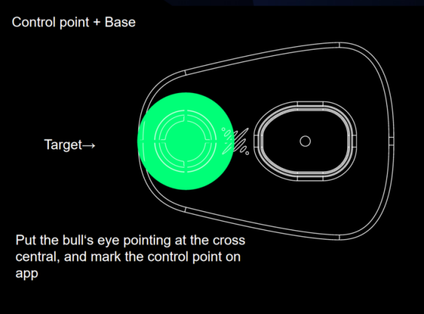
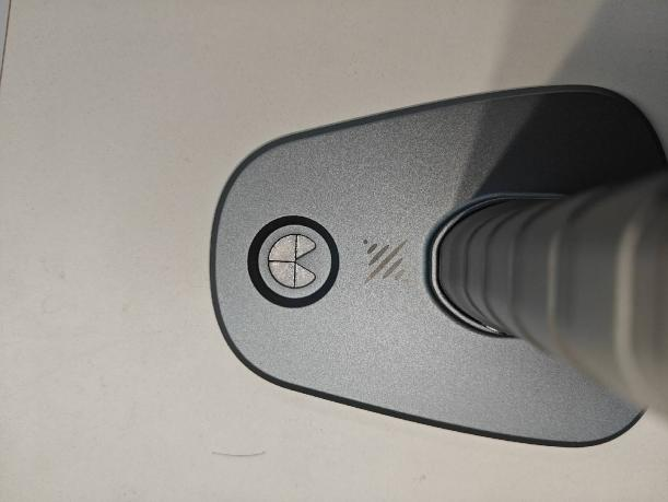
- Align with the control point: when passing a control point, align the sharp corners of the device base with the control point. You can use a standard control point target nail or target sheet.
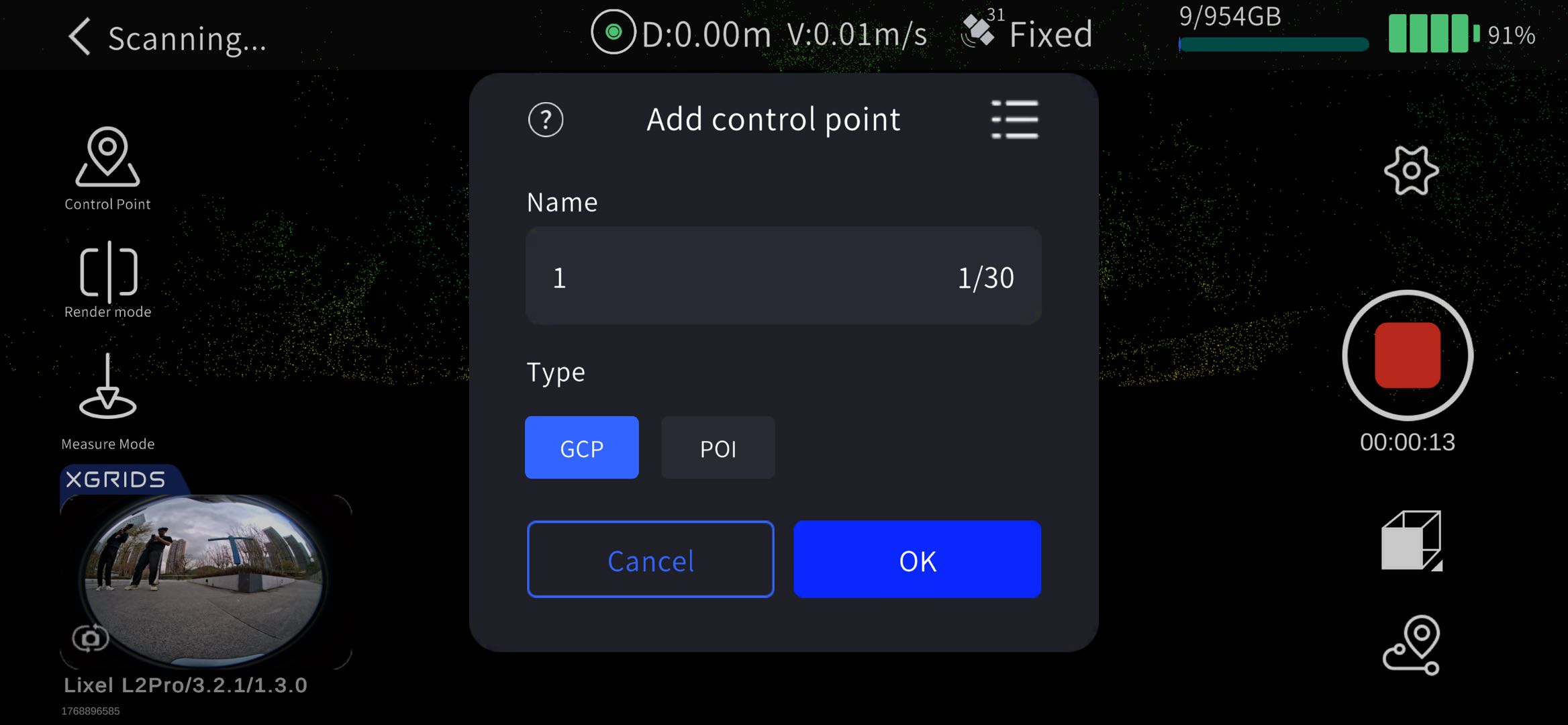
- Enter Control Point Mode: tap the Control Point Mode button on the left side of the screen.
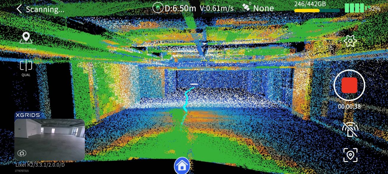
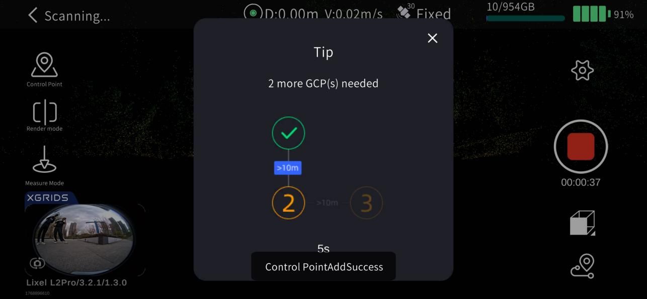
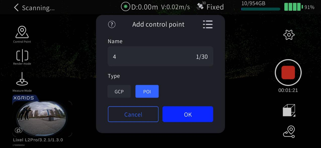
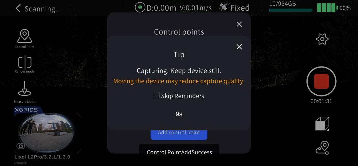
- Add a control point: tap the + button on the left, enter the control point number, and tap OK. The screen shows "Control point added successfully".
3. Notes
Name recording
- Note the name and order of the control points added in LixelGO.
- When later processing in LixelStudio, the imported control point file names must correspond one-to-one with the names recorded on the device.
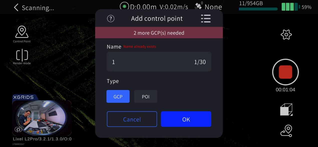
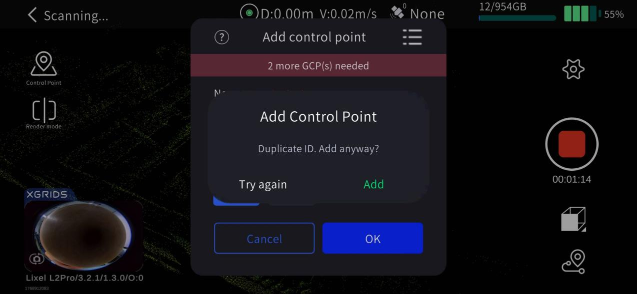
Duplicate names
- If a control point name is duplicated, the app pops up a reminder; decide whether to continue based on your situation.
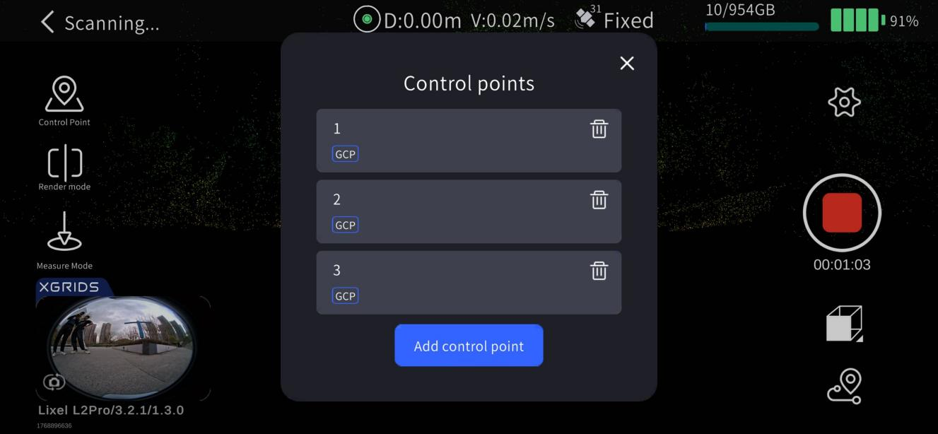
4. Control Point Management
- View the control point list: view collected control points in the Control Point List on the left side of the screen.
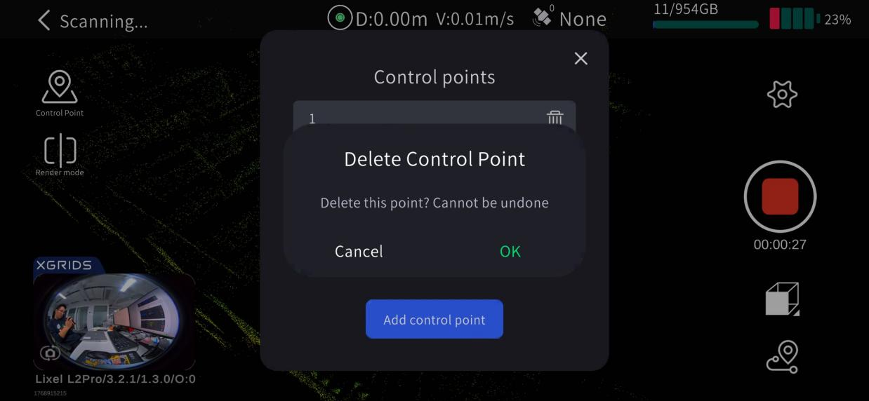
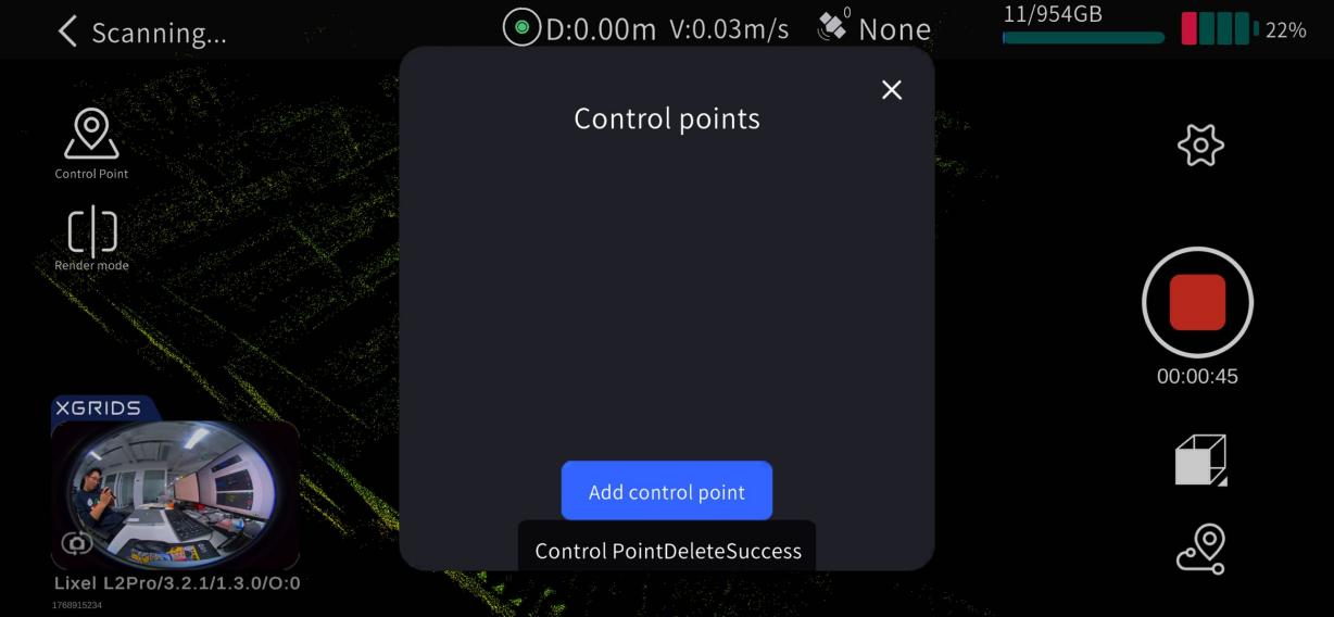
- Delete a control point: tap the delete button to the right of a control point.
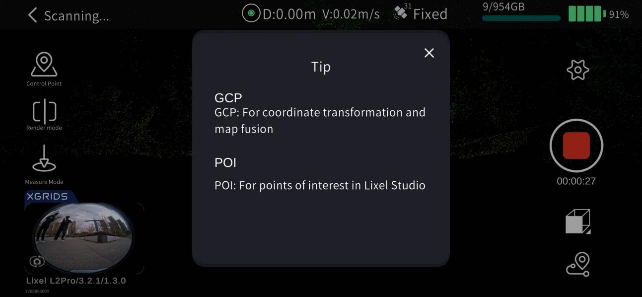
- Add a POI: tap the + on the left to add a POI.
5. Stop Scanning
Tap the red End Recording button on the right side of the screen. The device's green light flashes fast, then turns solid green when scanning is complete. You can then power off or start a second scan.
Office Work: Data Processing
See the LixelStudio user manual for details.
Through the RTK Module
With the RTK module, absolute coordinate information can be obtained directly during capture, improving the overall point cloud accuracy.
Note
For best results, use RTK mode to scan outdoors where the RTK signal is good.
Scanner Installation
The components used include the Lixel K2, battery, and base.
RTK module indicator light meanings
| Color | Status |
|---|---|
| Red | RTK not connected |
| Blue | RTK connected, not fixed |
| Green | RTK connected with a fixed solution |
Field Work: Scanning
1. Scan Route Planning
Plan the scan route based on the on-site environment, focusing on RTK signal reliability:
- Keep the RTK signal good along the route as much as possible.
- Keep segments where RTK is continuously disconnected or unfixed within 50 m.
Tip
A good RTK signal is key to post-processing accuracy. Watch the RTK indicator light during scanning and scan in the green (fixed solution) state whenever possible.
RTK status indicator light
| Color | Status |
|---|---|
| Red | RTK not connected |
| Blue | RTK connected, not fixed |
| Green | RTK connected with a fixed solution |
2. Connect the Device
Turn on the scanner and connect it via LixelGO. For detailed steps, see Device Activation and Connection.
3. RTK Account Settings
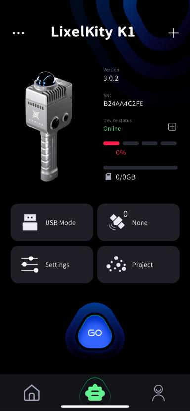
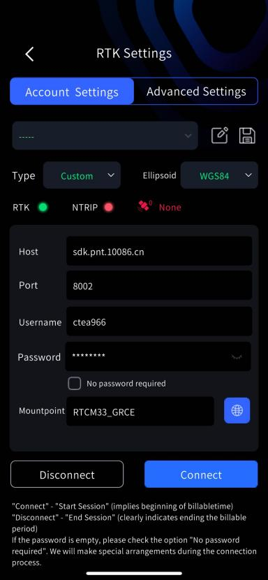
Enter the device screen and tap RTK settings (satellite icon button) to open RTK settings. Three account configuration methods are available: Qianxun SI, China Mobile, and Custom:
- Qianxun SI / China Mobile: log in with the corresponding account and password.
- Custom: enter the host, port, source node, etc.
4. RTK Account Management
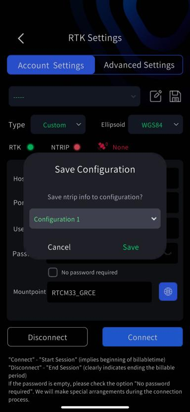
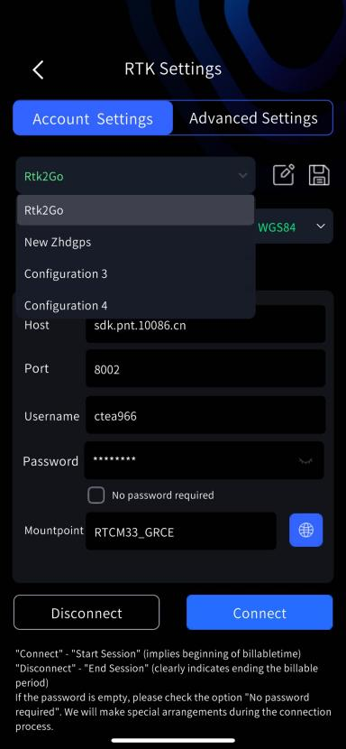
When you have one or more frequently used accounts, you can save RTK account information to the LixelGO app cache with the Save button.
- Enter RTK account information: host, port, source node, etc.
- Tap Save, choose a configuration item to save in the pop-up, and tap Save again. The RTK account information is saved to the LixelGO app cache.
- Tap Edit to rename a configuration item; after saving, the name is updated.
- Use the drop-down list to view saved RTK account configurations.
Note
- Currently Qianxun SI, China Mobile, and custom RTK are supported. To use a custom RTK, ensure the data format is a common format, otherwise it will not work.
- After the first setup, the device automatically records the RTK account and logs in automatically on subsequent use.
- Changing the RTK coordinate system takes about 5 minutes to apply; wait 5 minutes before starting work.
- The RTK module can obtain WGS84, CGCS2000, and ITRF2008 absolute coordinate systems; height is geodetic height.
5. RTK Advanced Settings
The K2 supports two GNSS modes:
| Mode | Function | Steps |
|---|---|---|
| RTK | Uses the RTK module's RTK function to receive differential data for real-time positioning and records it in the project file | Select RTK mode on the startup page; use the RTK module for project processing in LixelStudio |
| PPK | Uses the RTK module's PPK function to receive raw satellite data and records it in the project file | Select PPK mode on the startup page; use the PPK module for project processing in LixelStudio |
Satellite System Setting
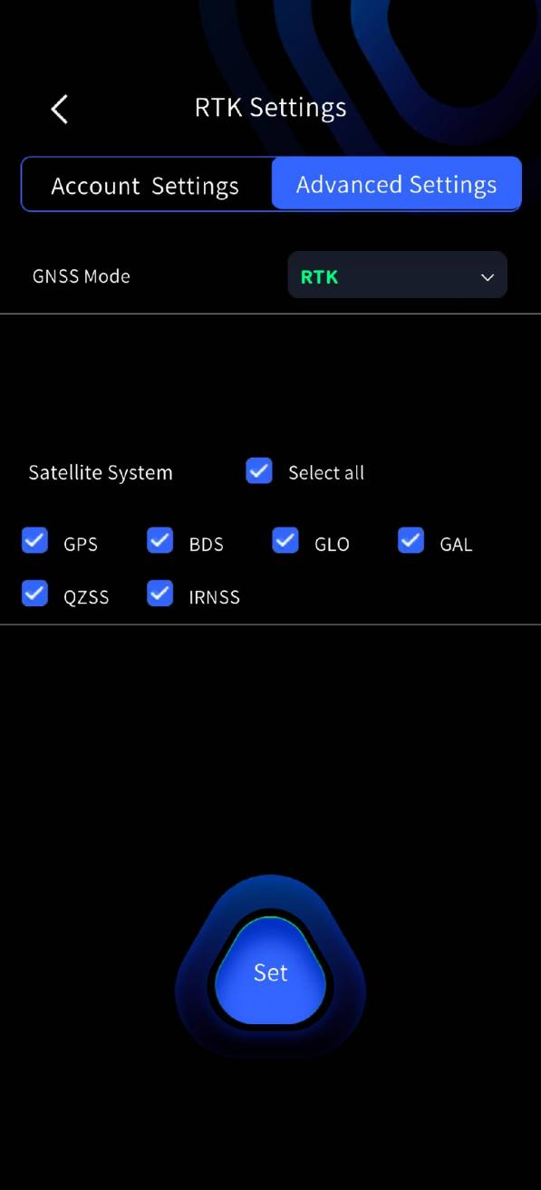
In RTK advanced settings, you can customize satellite system selection, supporting single, multiple, and select-all.
- Requirements: firmware version 2.3.0 or above, and RTK connected.
- How it works: entering RTK advanced settings automatically reads and displays the device's satellite system settings. Select the desired systems and tap Set; it takes effect immediately upon success.
6. Start Scanning
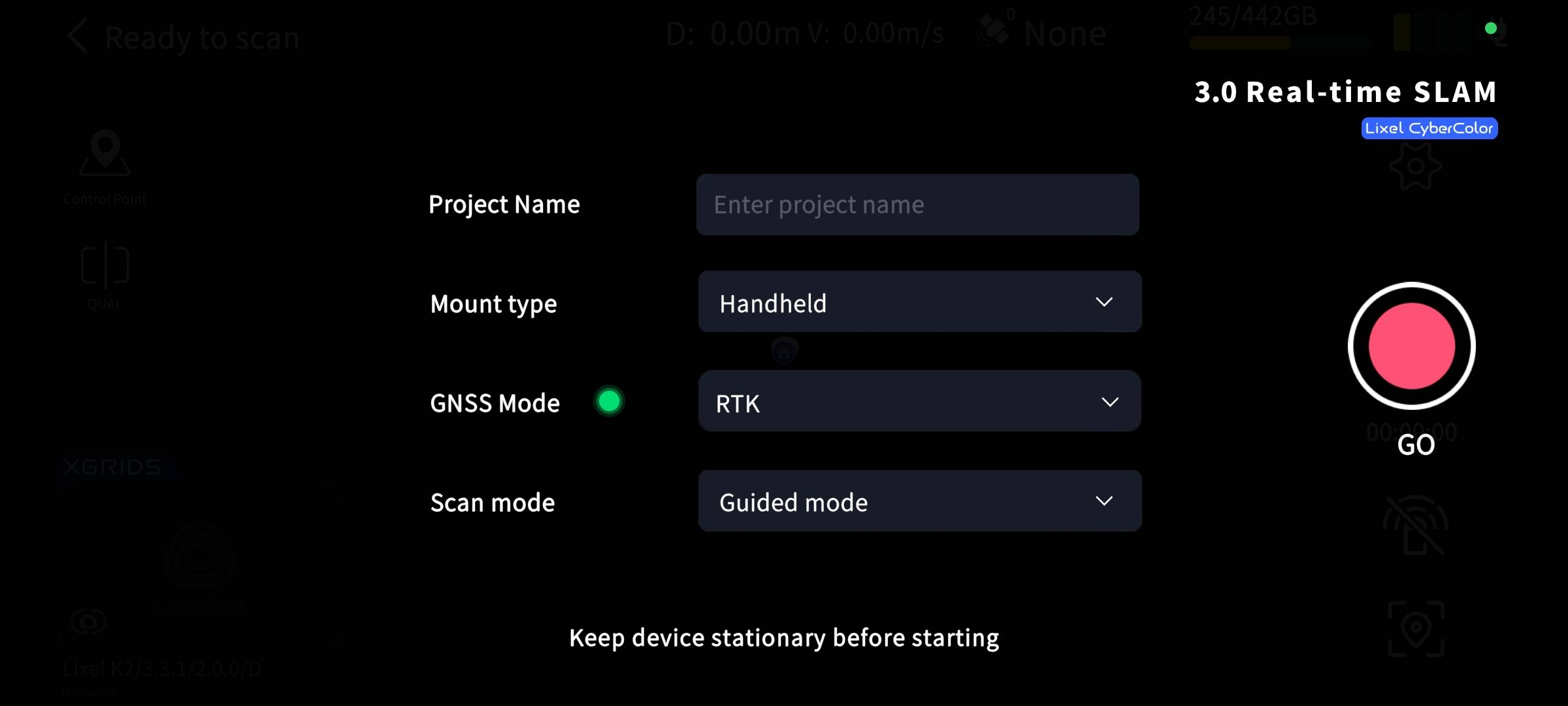
In RTK mode, wait for the RTK module indicator light to turn green and for LixelGO to show the RTK signal as Fixed before picking up the scanner and starting the scan.
Note
- RTK mode only supports outdoor scenes with an RTK signal; indoors, RTK cannot obtain a fixed solution.
- With a fixed solution, the module light is green; when it is blue, watch the satellite count.
- The satellite status in LixelGO must be
Fixedbefore you start; it cannot beNONE,Float, orSingle. - For accuracy, keep the device in a fixed-solution state most of the time, with more than 100 valid RTK data points, so coordinate conversion works properly in LixelStudio.
- Keep the scanner vertical while capturing; when walking, keep the tilt within 15°. In special cases (scanning small-space ground or ground targets), the tilt must not exceed 30°.
- Keep the scan space larger than 10 m.
- For accuracy verification, the capture route must be ≥ 100 m and not a straight line.
- To ensure post-processing accuracy, keep the continuous unfixed RTK distance < 50 m.
7. Stop Scanning
Tap the red End Recording button on the right side of the screen. The device's green light flashes fast, then turns solid green when scanning is complete. You can then power off or start a second scan.
Office Work: Data Processing
See the LixelStudio user manual for details.