
General Capture Principles
Regardless of which device you use, the following principles always apply:
Parallax Coverage
3DGS reconstruction relies on observing the same point from different angles to triangulate its spatial position. Key requirements:
- Multi-angle coverage: Capture each area from at least 3 different angles
- Adjacent frame overlap: Maintain 60%–80% image overlap
- High/low angle variation: Introduce pitch variation (high, eye-level, low)
- Avoid symmetric paths: Asymmetric motion helps eliminate reconstruction ambiguity
Parallax Principle Animation
Motion Guidelines
| ✅ Recommended | ❌ Avoid |
|---|---|
| Slow, steady movement (0.5–1 m/s) | Fast movement (>2 m/s) |
| Keep the camera always moving | Rotating in place (pure pan/tilt) |
| Continuous, uninterrupted capture | Frequent pausing/starting |
| Lateral panning + forward/backward movement | Straight-line forward only |
| Serpentine path to cover the area | Single straight line through |
Core principle: Do not rotate the camera in place. Pure rotation produces no parallax and leads to reconstruction failure. Always change your viewpoint while moving. Standing still for long periods also does not improve results.
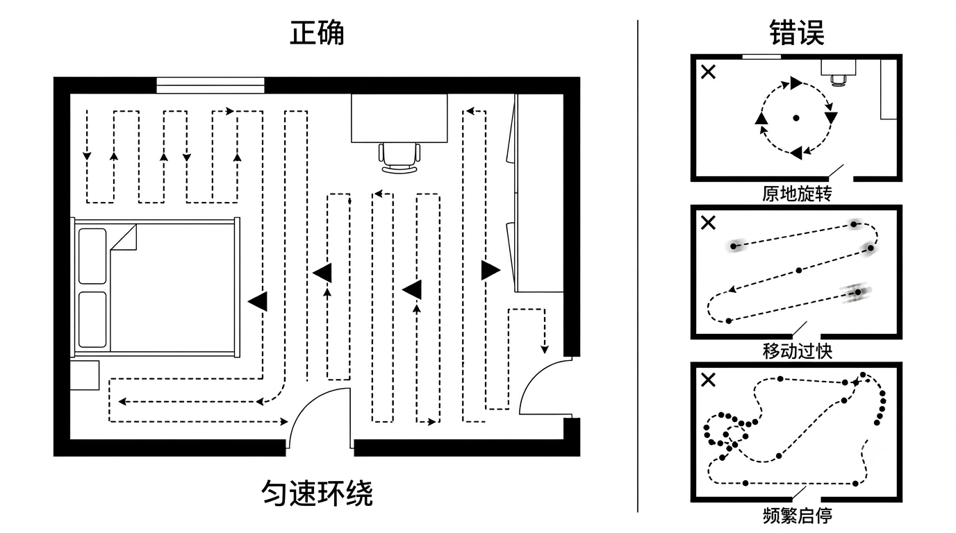
Correct vs Incorrect Motion Paths
Serpentine Movement
Use a serpentine (zigzag) path instead of a single straight line. Unless the capture area is an extremely narrow corridor, use a serpentine path to achieve fuller multi-angle coverage.
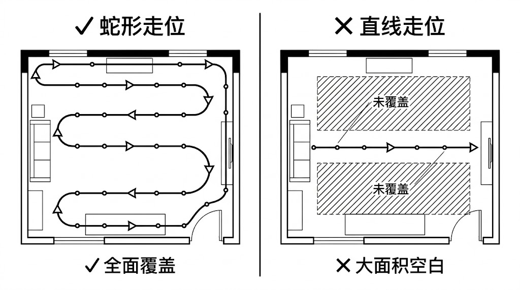
Serpentine vs Straight-line Movement (top-down view)
Speed by Scenario
The general movement speed should not exceed 1 m/s (PortalCam recommended not to exceed 0.5 m/s). In the following scenarios, further reduce speed to 0.3 m/s:
- Indoor spaces, corridors, or when the target is close to the lens
- Dim areas with poor lighting
- Doorways and indoor/outdoor transition zones
- Turning, rounding corners, and other rotation-involving maneuvers
- Areas with sudden lighting changes such as motion-sensor lights and windows
Saturated Capture
For scenes with significant occlusion, or when clarity is the priority, consider saturated capture:
- Walk as many different routes through the scene as possible
- Adjust the scanner height and re-scan the same location from different viewpoints to ensure sufficient data overlap and complete coverage (line-of-sight difference within ±40°)
- Standing still at one location does not improve reconstruction — always keep moving
Loop Closure
Loop closure is a key technique for improving the stability of large-scale reconstruction. On top of covering the capture area, arrange loop-closure paths appropriately.
What Is a Valid Loop Closure
Return to a similar position captured previously, with a similar camera orientation — the line-of-sight difference should not exceed ±40°.
Only when these conditions are met can the algorithm successfully detect the loop closure and perform global optimization.
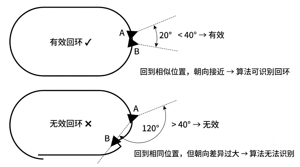
Valid loop closure: similar position + line-of-sight difference ≤ ±40°
Loop Closure Principles
- Start-end loop closure: When conditions allow, the start and end points of the capture should form a closed loop at the same location
- Mid-capture loop closure: In the following situations, arrange at least one loop closure mid-capture:
- When start-end loop closure cannot be achieved
- When capturing larger-scale scenes
- When the scene has significant occlusion or narrow structures
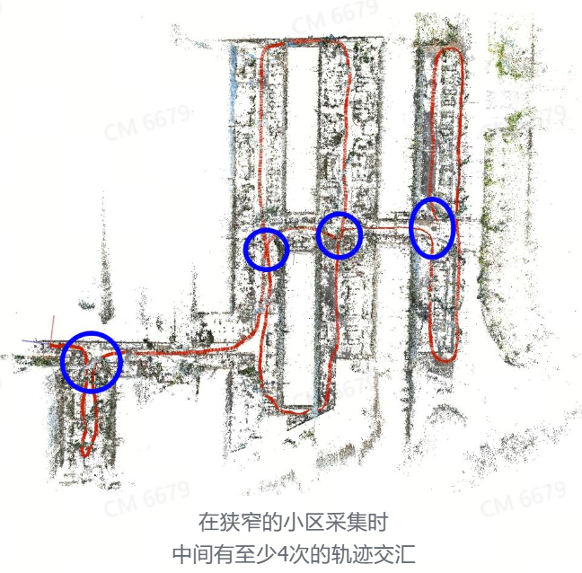
Loop closure path arrangement: start-end and mid-capture loops
When capturing large scenes with the K2, ensure there is at least one trajectory overlap every 500 m to avoid reconstruction layering. If scene constraints make this impossible, use RTK or provide relative control points beyond 500 m.
Camera Orientation
Pitch Angle Limit
During capture, the device pitch angle should stay within -60° to +60°. Avoid pointing the device straight up or straight down.
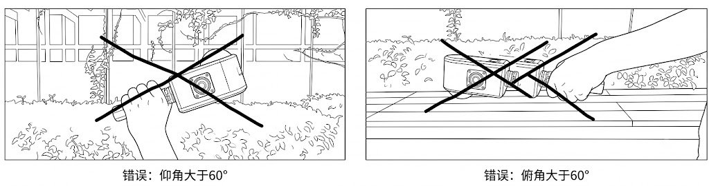
Device pitch angle range (-60° to +60°)
Minimum Shooting Distance
The minimum distance between the device and the captured object is 0.5 m (about the length of a forearm). Also avoid entering overly narrow areas; keep the device at least 0.5 m from surrounding surfaces.
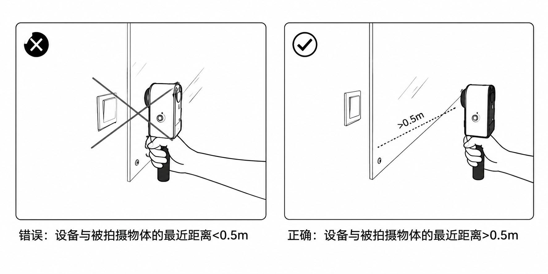
Minimum shooting distance ≥ 0.5 m (about a forearm)
Adjusting Orientation by Target of Interest
Ensure key targets of interest have sufficient detailed image data while also covering the overall scene:
| Target of Interest | Orientation Strategy |
|---|---|
| Ceiling pipes | Provide some upward angle to ensure the lens covers overhead pipelines |
| Text / nameplates | Point the lens toward and close to the text, moving slowly in an S-shape |
| Sculptures / objects | Point the lens toward the object and orbit around it |
| Ground details | Cover ground textures from a top-down angle |
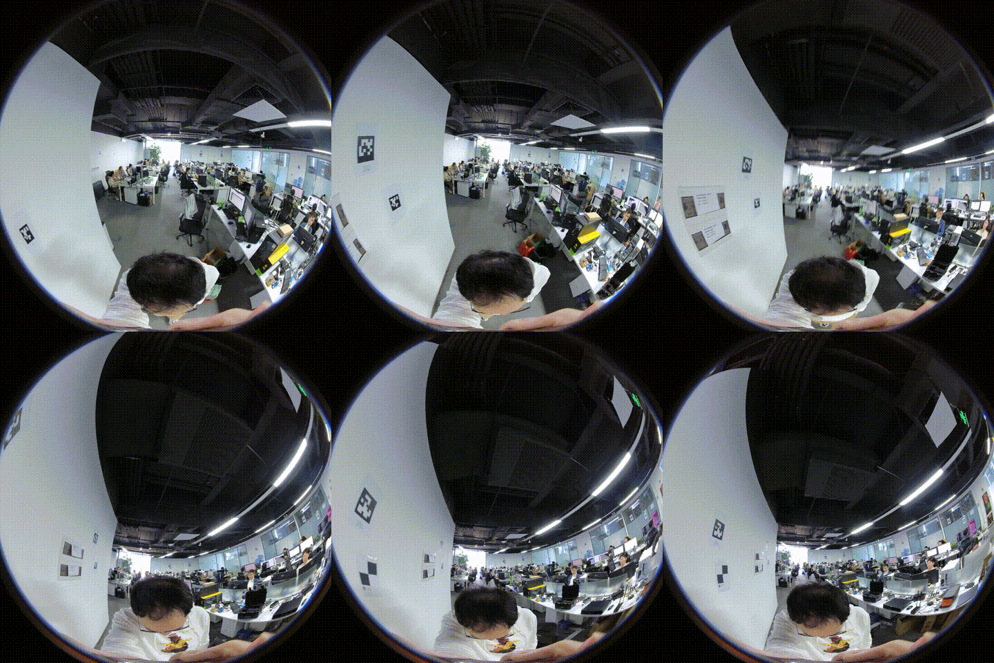
Provide pitch angle, focus on the ceiling
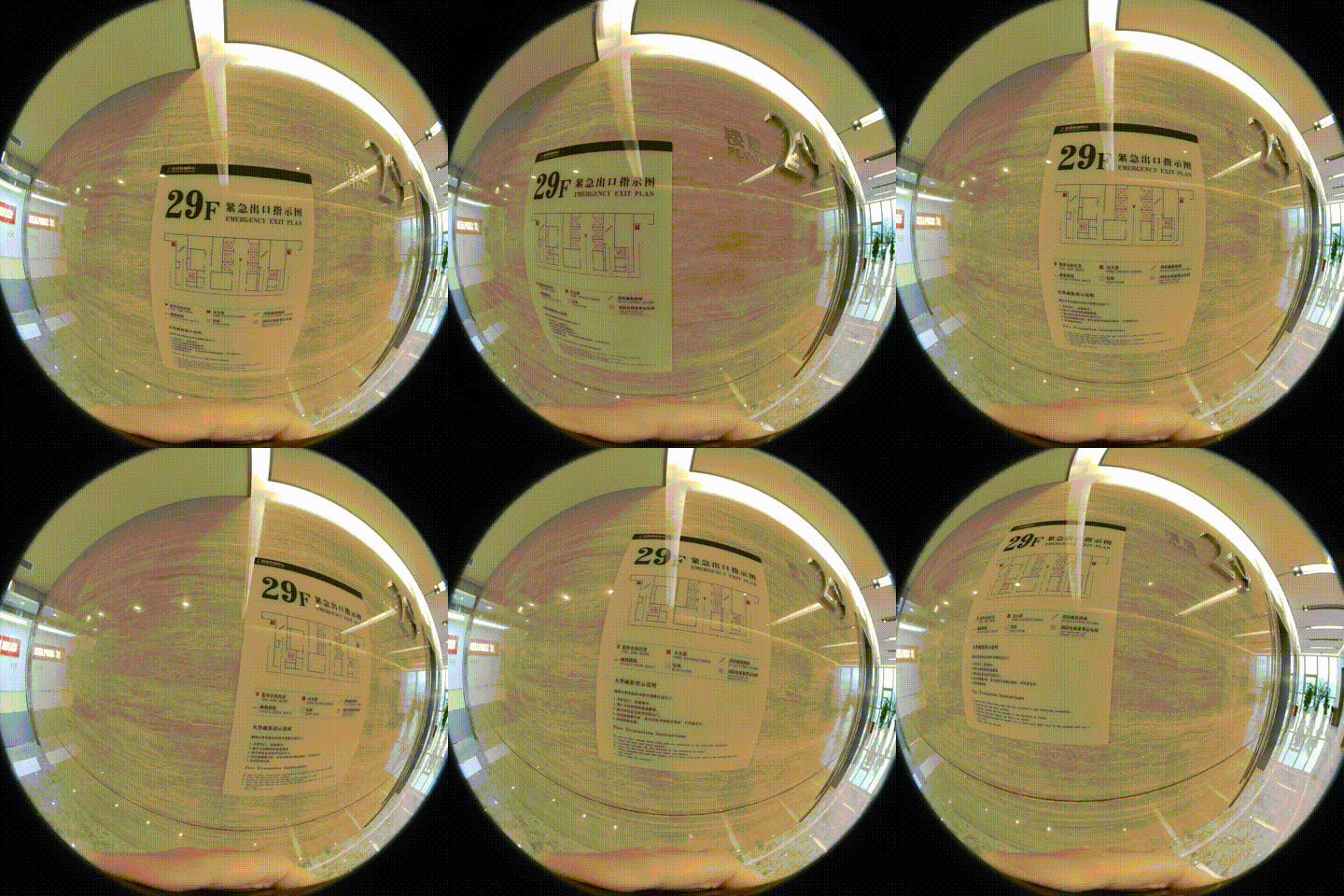
Slow S-shape scanning, focus on text details
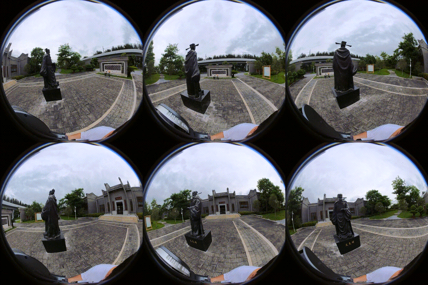
Orbit scanning, focus on a specific object
When unsure of the target of interest, saturated capture (multiple routes, multiple angles) is often the most effective strategy.
Initialization Position
For captures without RTK, the reconstructed rendered scene will use the initialization position (where the device started scanning) as the initial viewpoint of the rendering camera. Therefore:
- Choose the main display area of the scene as the initialization location
- Capture the area around the initialization point in detail to ensure all viewpoints of the main scene are clear and blur-free
- For PortalCam, ensure the front-view area is in good condition at initialization, avoiding crowds, traffic, and other highly dynamic areas
When using RTK, the initial position of the rendering camera is the first valid RTK fix.
Lighting Requirements
| Condition | Recommendation |
|---|---|
| Indoor | Turn on all fixed lights, open curtains, avoid using flash |
| Outdoor | Overcast is best; on sunny days avoid harsh midday shadows |
| Exposure | Lock exposure and white balance whenever possible (manual mode) |
| Insufficient light | Be sure to reduce movement speed to 0.3 m/s and increase angle coverage |
| Avoid | Backlighting, lens glare, drastic light/dark changes |
3DGS assumes the scene is static. Moving shadows and flickering lights both produce artifacts.
Lighting Consistency for Multi-segment Fusion
When performing map fusion, aerial-ground map fusion, or HD Enhancement, the lighting across different data segments should be kept as consistent as possible:
- All data segments should be captured within 2 hours if possible
- Avoid stitching under drastic lighting changes such as spanning morning/evening or sunny/overcast conditions
- When stitching multiple segments captured over a long interval, prioritize areas with clear textures and stable lighting as overlap regions
Scene Preparation
- Remove or fix all potentially moving objects (people, pets, curtains in the wind)
- Turn off electric fans and secure lightweight items near AC vents
- Ensure the floor is clean with no large reflective puddles
- Glass/mirror areas: avoid or cover them when possible (3DGS has limited handling of specular reflections)