
Aerial-Ground Map Fusion Workflow
Overview
This article summarizes the capture methods and data reconstruction workflow for Aerial-Ground Map Fusion in XGRIDS LCC Studio.
Aerial-Ground Map Fusion combines ground data captured by a ground mobile scanner with aerial imagery captured by devices such as DJI drones, building an LCC model (3DGS) that integrates both ground and aerial coverage. It is suited to complete modeling of complex terrain such as large sites, building clusters, and scenic areas.
By using a drone to supplement capture of areas that are hard to reach from the ground, such as building rooftops, the whole site, and the upper parts of structures, you can build a 3DGS model that covers from the ground to the air with almost no blind spots.
Supported Devices
Recommended XGRIDS Devices
The L, K, and P series ground SLAM scanners are supported; L2 Pro and PortalCam are recommended. The device and RTK combinations are described below:
| Ground data | Drone data | Recommendation | Notes |
|---|---|---|---|
| L series + RTK | Drone RTK | ★★★★★ | Highest accuracy, recommended |
| P series + Aerial-Ground Map Fusion GCP | Drone RTK | ★★★★ | Recommended |
| P series + Aerial-Ground Map Fusion GCP | Drone without RTK | ★★★ | Recommended; consumer drones can be used |
| L series + RTK | Drone without RTK | Not recommended; reconstruction may fail or split into layers |
Note:
- Good GNSS reception is required when capturing with RTK enabled.
- Support may change with LCC Studio, Lixel Go, LCC Scan App, and device firmware.
- When both the ground device and the drone capture with RTK enabled, they must use the same coordinate system (WGS84 or CGCS2000).
- P series devices require Aerial-Ground Map Fusion tie points; otherwise reconstruction may fail or fusion quality may be poor.
Recommended Drone Models
For aerial photography, choose a model suited to photogrammetry scenarios, such as the high-resolution Enterprise series from DJI. Models that support high-accuracy shooting-position recording through solutions like TimeSync are especially recommended.
| Recommended | Acceptable | Not recommended |
|---|---|---|
| DJI P1 (Zenmuse P1) | DJI M4E / M3E / P4R | Low-resolution or non-photogrammetry models such as M4T / M3T / FC3582 / M30 / M30T |
Ground Data Capture
Ground data is captured with an XGRIDS ground mobile scanner, following the normal outdoor capture workflow.
Basic Requirements
- Scan with an XGRIDS device in the usual way, focusing on areas such as building bases, ground textures, and entrances.
- Stitching of multiple ground capture segments is supported; the capture requirements are the same as for Map Fusion.
- Make sure the scanning path passes through each drone takeoff and landing point (yellow circles in the image below), leaving an overlap area for later aerial-ground connection.
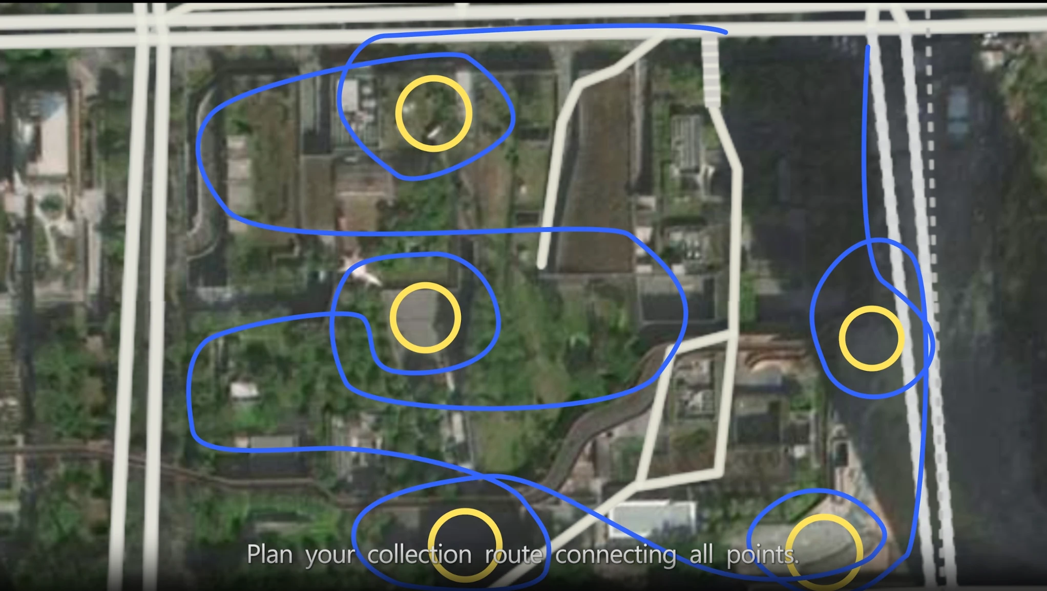
The scanning path passes through each drone takeoff and landing point, leaving an overlap area
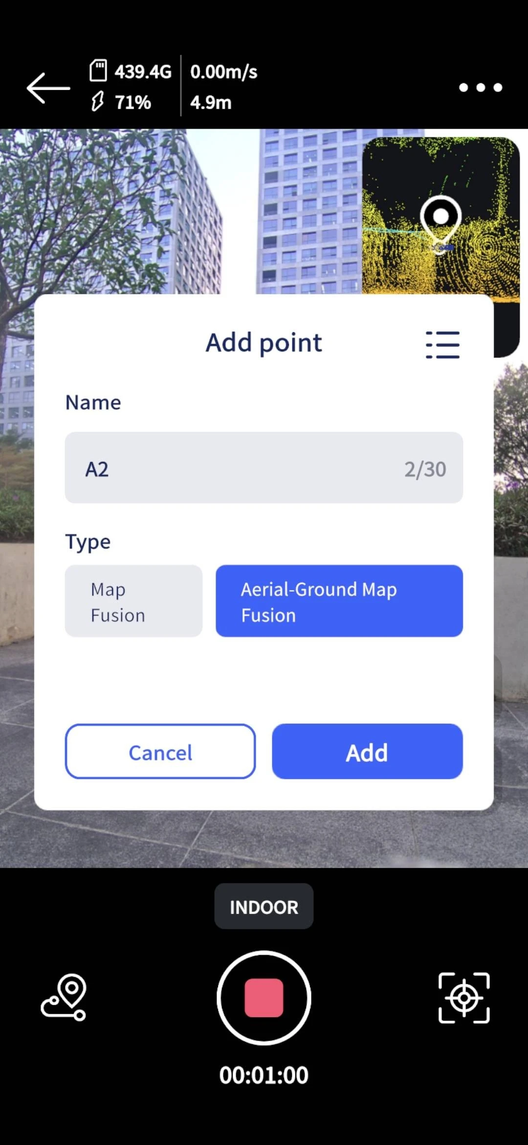
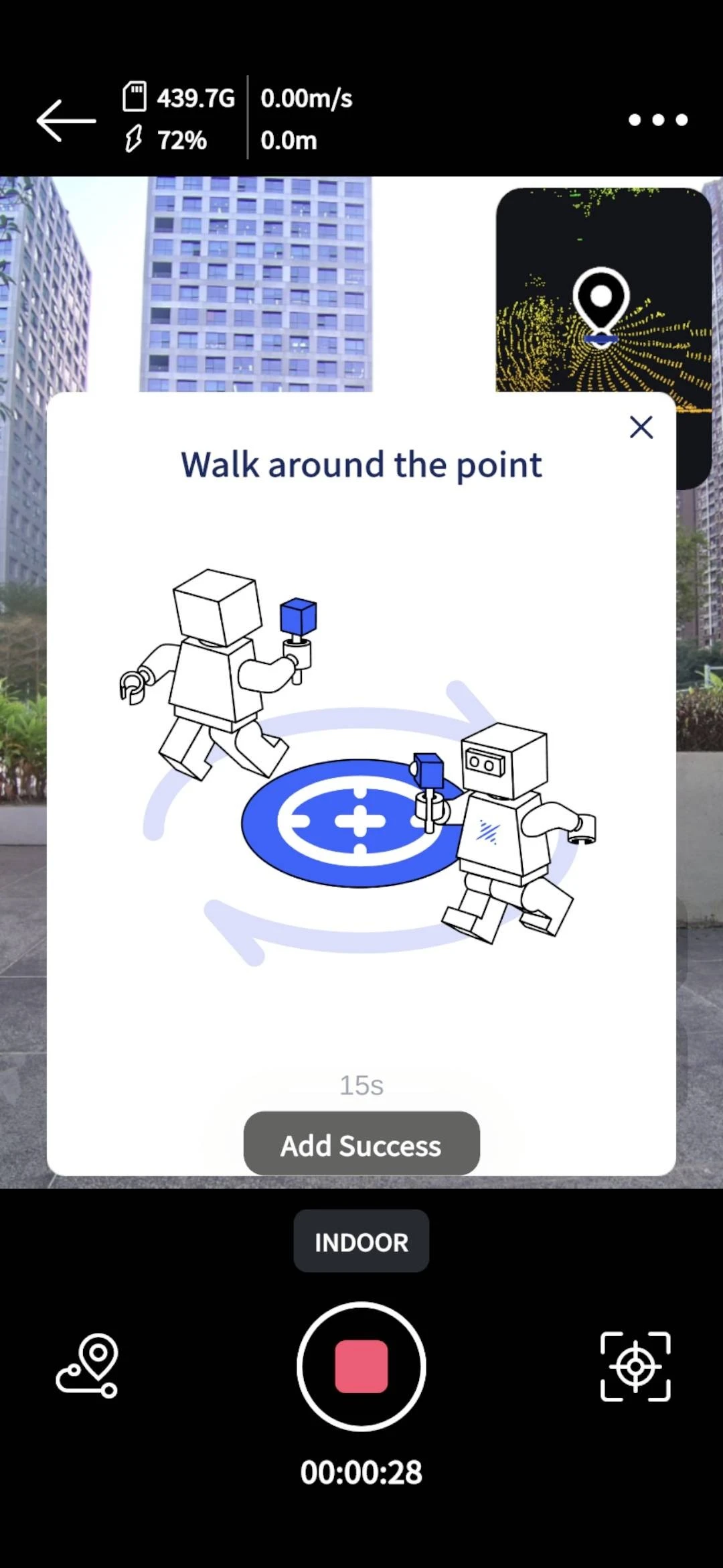
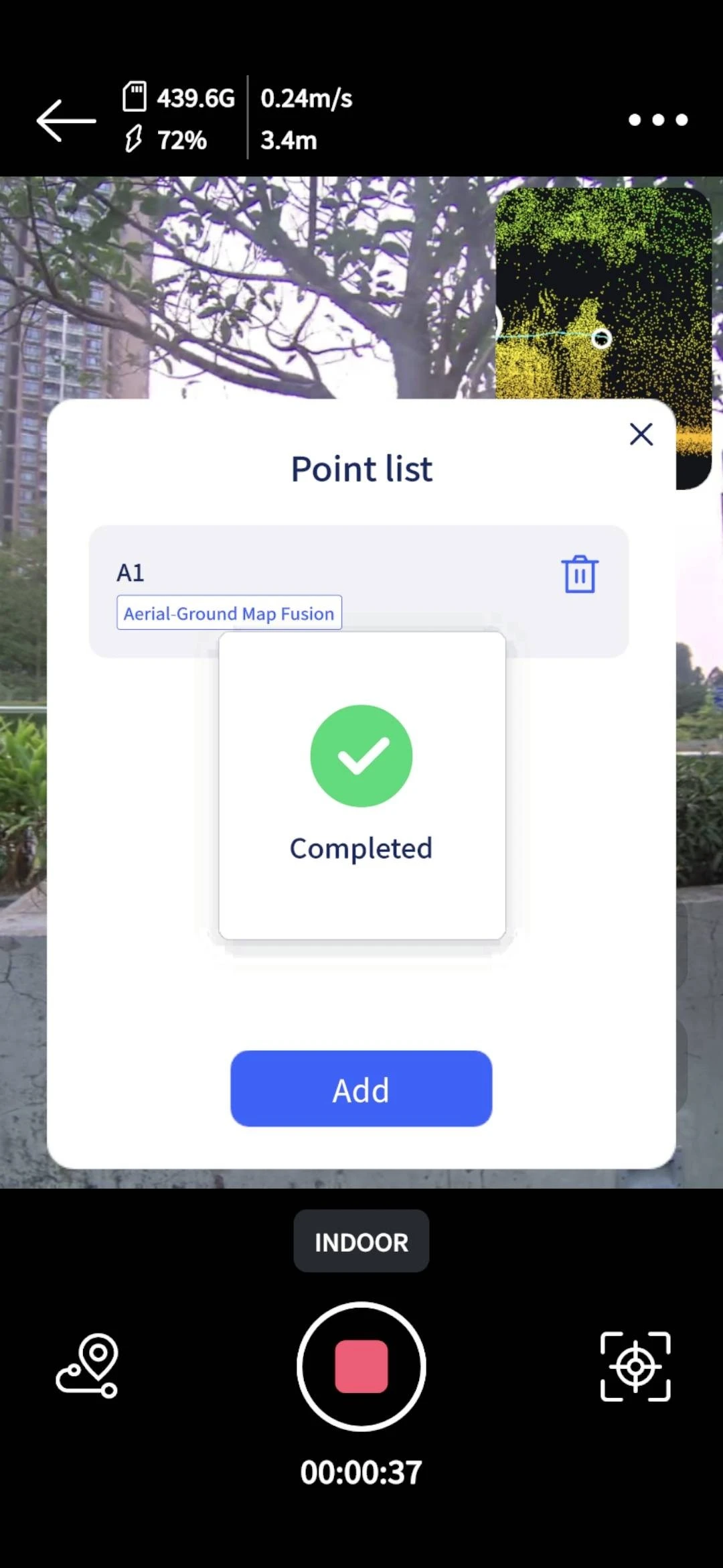
P series devices require Aerial-Ground Map Fusion tie points to be placed in LCC Scan; L series devices do not. The specific steps:
Multi-height Coverage
Following the indoor "three-angle" approach, the device lidar field of view during ground scanning should cover three angles, especially for building facades:
- Low: ground details
- Eye level: main facade
- Upward: high structures
RTK Notes
- Before powering on the device, make sure it is firmly mounted, the RTK does not wobble, and the screws are not loose.
- After powering on, connect to Lixel Go and log in to the Cors service, wait for the RTK signal to reach the fixed solution (Fix) state, and keep Fix as much as possible throughout.
- The Lixel Go coordinate system currently supports only the WGS84 / CGCS2000 ellipsoid.
Aerial Data Capture
Aerial data is captured by drone, broadly following the normal oblique photography requirements. Aerial data capture comes in two approaches, with RTK and without RTK; choose one based on your device combination.
Approach with RTK (Recommended)
In principle, the real-time kinematic (RTK) approach is recommended. Make sure both the ground scan and the drone carry accurate position information, then use that position information to complete position calibration in LCC Studio.
- The drone (including takeoff and landing) and the ground SLAM device must both enable RTK, with fully consistent coordinate systems (WGS84 or CGCS2000).
- Keep the Fix signal state as much as possible throughout for both the drone (including takeoff and landing) and the ground SLAM device, to improve fusion accuracy and quality.
- The reconstructed model result will contain absolute coordinate information and can be exported for use in GIS platforms.
- P series devices have no RTK module; ground capture does not need to enable this feature, and post-processing adapts automatically.
Taking the M4E as an example: at an open location within the survey area with no tall-building obstruction, power on the remote controller, pull down the screen, and tap WiFi to connect to a hotspot network. Enter the flight interface of the DJI Pilot 2 app (turn off the pre-flight check first), tap the three-dot symbol in the top-right corner, then tap "Precise Positioning Settings" in the bottom-right corner: set the coordinate system and confirm that RTK is connected and positioning is Fix.
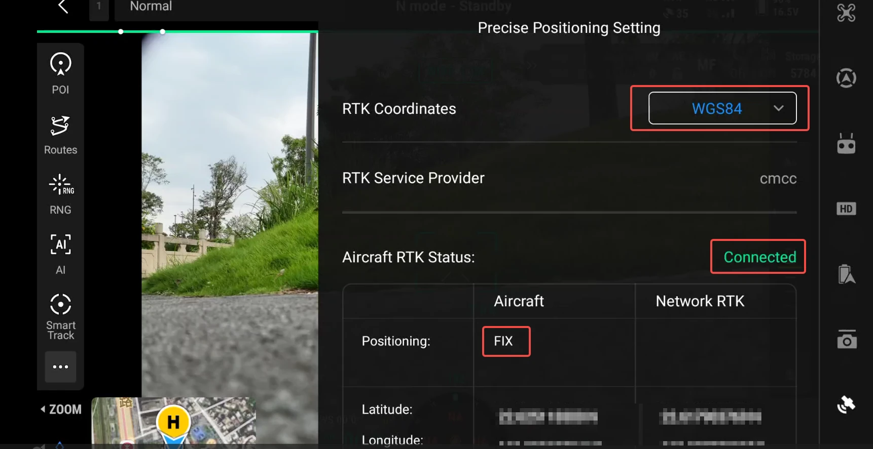
Precise positioning settings: confirm the coordinate system and RTK Fix status
Common Route Capture Requirements
Overhead route shooting above building rooftops
| Item | Recommendation |
|---|---|
| Flight mode | Smart oblique capture recommended, to ensure full coverage |
| Overlap | ≥ 85% |
| Flight altitude | Flying at the lowest allowed safe altitude works best; unless otherwise restricted, do not fly above 50 m |
| Single / multiple layers | Simple small-to-medium scenes: fly a single lowest-safe-altitude layer; complex large scenes: fly 1-2 extra layers above the lowest layer |
| Multi-layer height difference | The height difference between two adjacent layers should not exceed 2x |
| Flight speed | ≤ 5 m/s, steady and uniform |
| GSD | Below 1 cm |
| Gimbal angle | About 45° (oblique photography); smart oblique enabled |
| Focal length | Use a single focal length throughout |
Continuing with the M4E as an example, tap to enter the route library and tap the "+" in the top-right corner to create a new route:
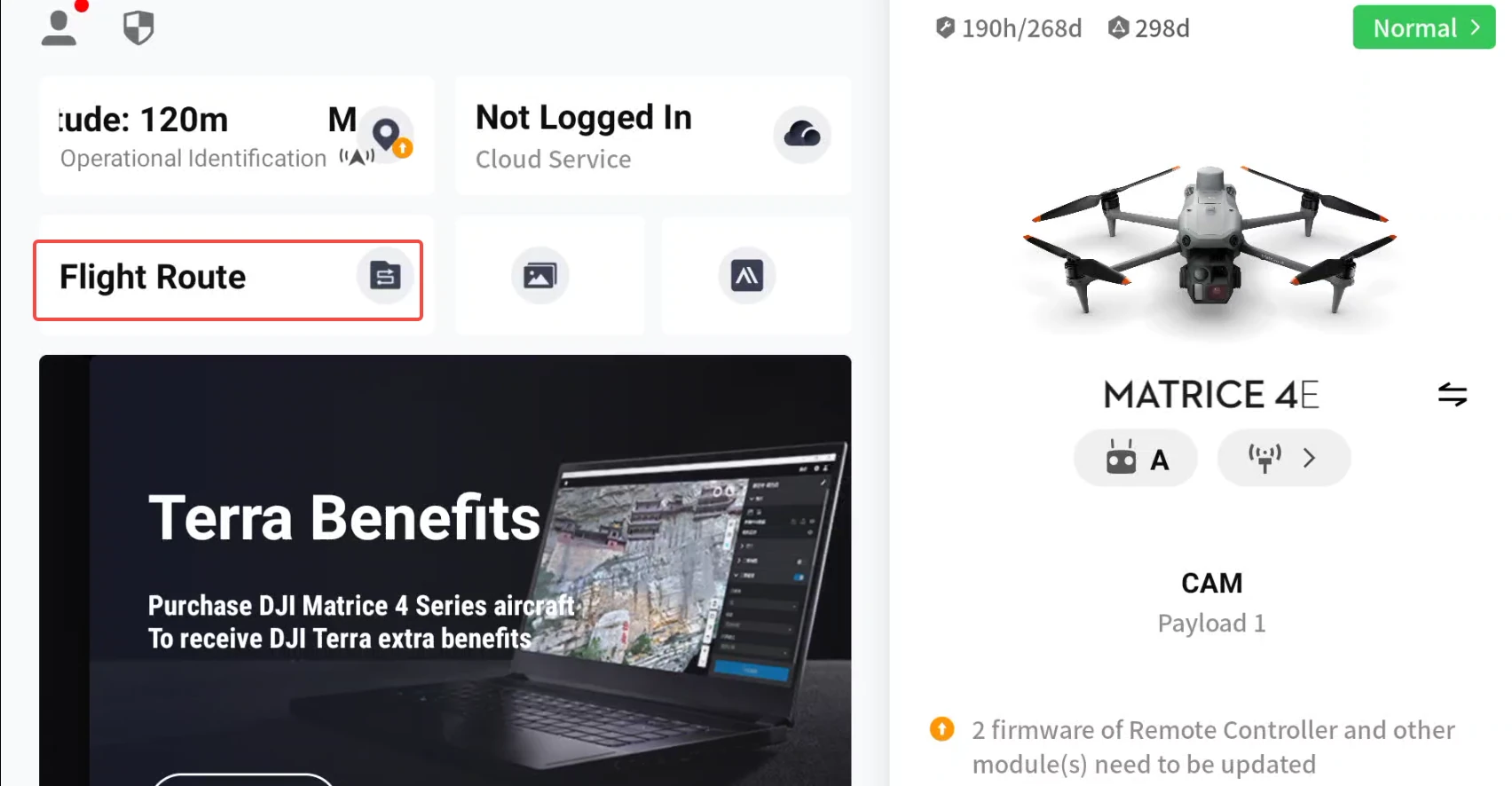
Enter the route library
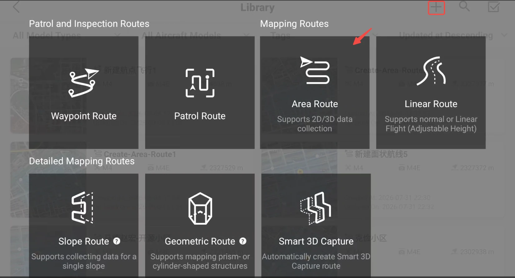
Create a new route
Tap on the map to plan the survey area boundary:
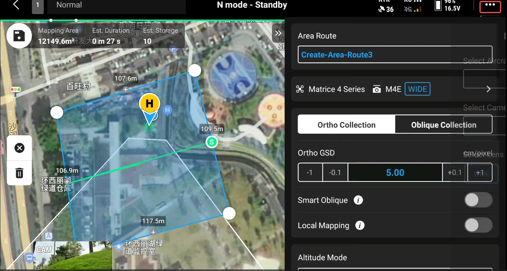
Plan the survey area boundary
Following the specification, set the oblique route capture GSD, turn on smart oblique capture, set the camera shooting tilt to 45°, and set the flight altitude:
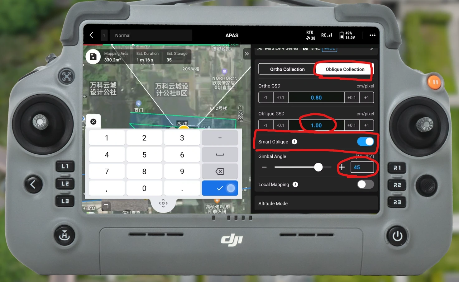
Set the oblique route: GSD, smart oblique capture, 45° tilt, flight altitude
In the advanced settings, enter the shooting overlap in both directions.
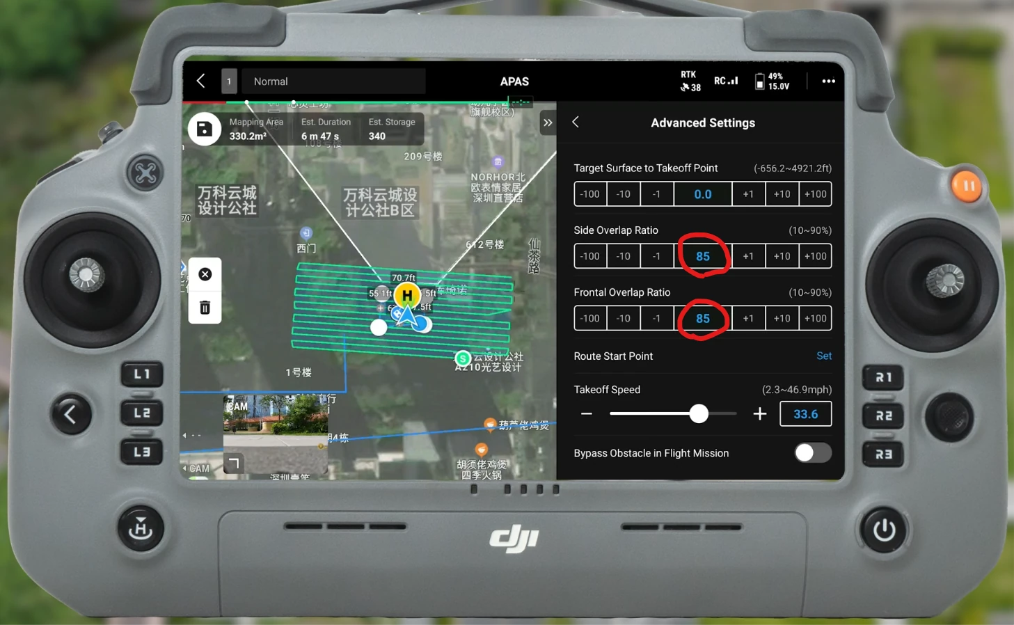
Enter the shooting overlap in the advanced settings
Tap Save Route in the top-left corner, then tap again to upload the route and execute the flight mission, until the drone returns to the ground.
Orbiting shots of building facades (if needed)
If the facades (exterior walls) of a high-rise building need dedicated coverage, the drone supplements it by orbiting around the building exterior:
| Item | Recommendation |
|---|---|
| Flight distance | 3-5 m from the building facade |
| Flight altitude | At 1/2 to 2/3 of the building height (to ensure the lens covers top and bottom) |
| Lens orientation | Always facing the building exterior wall |
| Flight speed | ≤ 5 m/s, steady and uniform |
| Coverage requirement | All four sides of the building must be orbited; slow down at corners for multi-angle coverage |
| Multi-layer orbiting | For high-rise buildings, orbit once at each of 2-3 height layers |
Note: Area-route smart oblique capture can only cover rooftop and ground top-down views. Building facades (windows, wall details, entrances) need to be supplemented by orbiting.
Common Takeoff and Landing Connection Requirements
Whether the aerial data and ground data can be fused successfully depends on the existence of an overlapping connection area between the two datasets. The takeoff and landing part is exactly this connection data and is key to fusion quality.
Choosing Takeoff and Landing Point Locations
| ✅ Correct | ❌ Wrong |
|---|---|
| During survey planning, choose unobstructed drone takeoff positions, evenly distributed within the survey area, ideally one every 50 m, surrounding the ground SLAM survey area on all sides | Placed all on the same side |
| Relatively open in front, with no line-of-sight obstruction within 10 m | Close to a solid-color wall or reflective surface |
| Facing distinctive buildings or facades | Close to trees or repetitive structures |
| Multiple takeoffs and landings facing the same subject in the scene | Facing an indistinct background |
Number and Distribution of Takeoff and Landing Points
- For each scene, add points appropriately following a "four corners + center" distribution; more is better than fewer.
- For larger scenes with sides over 100 m: ensure at least 1 takeoff-and-landing shot within every 50-100 m.
Takeoff and Landing Shooting Requirements
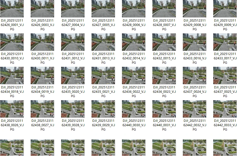
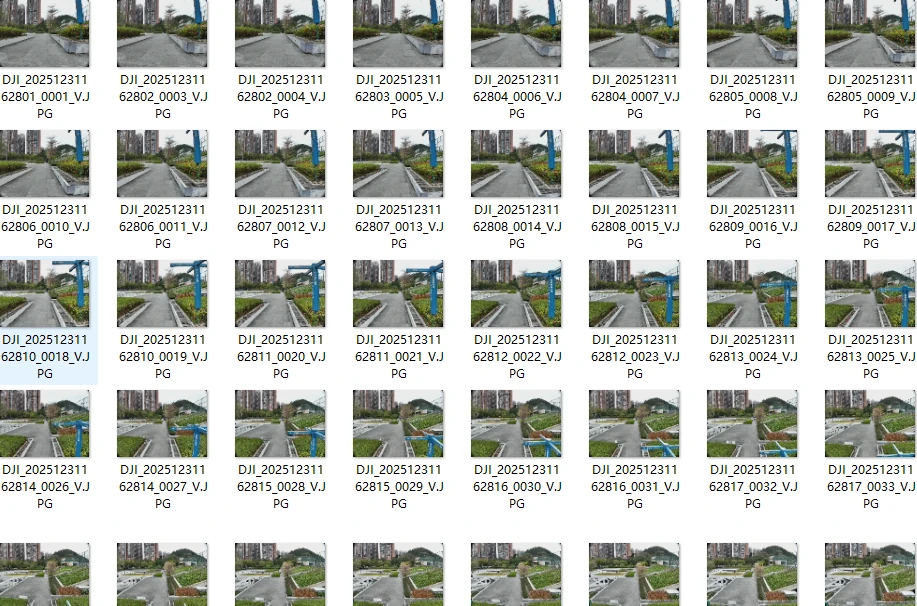
Each takeoff and landing must provide continuous images from about 1.5 m above the ground up to the aerial flight altitude, and meet these conditions:
- Ground eye-level shooting: the position and viewing angle must have sufficient overlap with the trajectory captured by the ground device. Since the drone FOV is usually smaller, while prioritizing the viewing angle you may move slightly farther from the subject to ensure coverage, but no more than 1.5x the ground capture distance. Adjust the drone orientation so that its subject and framing stay as consistent as possible with the images captured by the ground device.
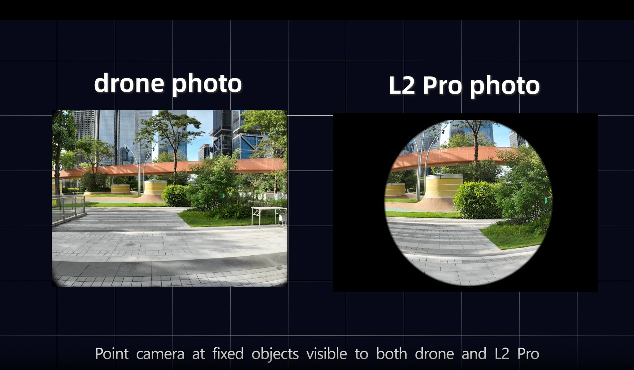
Ground eye-level shooting, overlapping with the ground capture trajectory
- Aerial top-down shooting: the position and viewing angle must have sufficient overlap with the aerial route images.
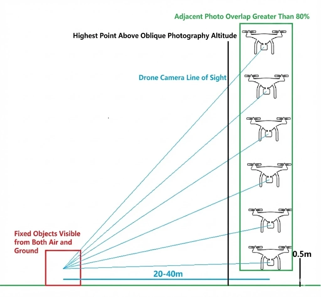
Takeoff and landing shooting schematic: continuous connection from the ground to the air
- Smooth transition: from the ground to the air, the camera position and angle must transition smoothly, with an overlap of ≥ 85% between adjacent images.
- Highest takeoff/landing point: the highest point of each takeoff-and-landing shot should exceed the flight altitude of the oblique photography route by about 5 m.
- Shoot each takeoff and landing point from three or more directions, to improve the success rate of connecting the aerial and ground data.
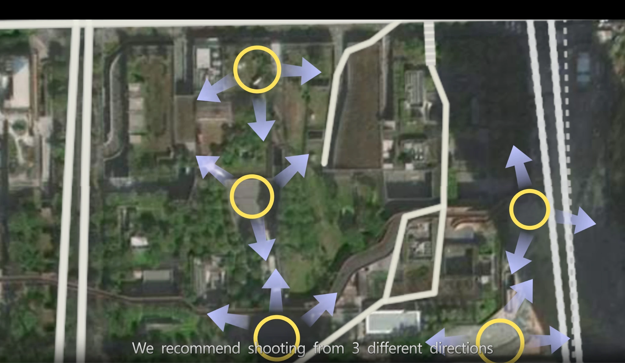
Shooting the same takeoff and landing point from multiple directions
Continuing with the M4E as an example, place the drone at a takeoff and landing point, enter the flight interface, and keep the RTK status at Fix. With the nose (camera) oriented consistently with the ground capture, take off to a height of 0.5-1.5 m. Operate the drone to rise vertically, aim at a fixed target ahead, and shoot manually or use point tracking, orbiting, or similar methods to shoot at timed intervals:
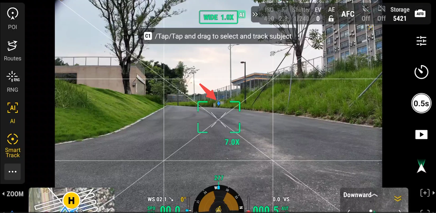
Rise vertically and shoot aiming at a fixed target ahead
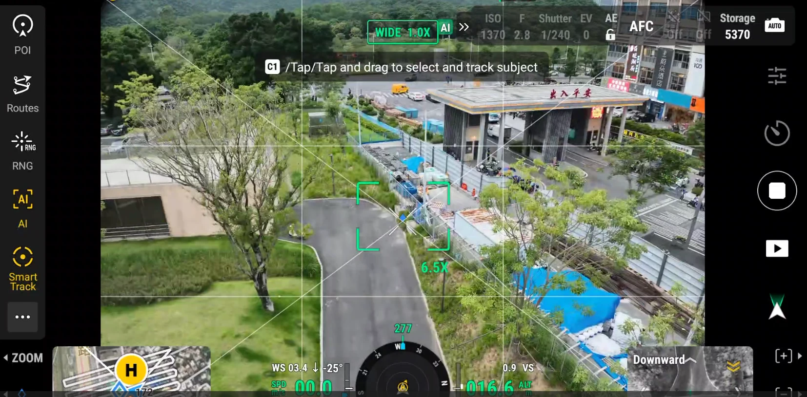
Continuous shooting at a takeoff and landing point
After reaching the oblique photography route altitude, operate the drone to turn around, then descend vertically in the air while shooting photos. After completing the first takeoff and landing point, keep the current shooting mode, continue to the next takeoff and landing point, and complete its shooting.
Approach without RTK (P series only)
If you do not use RTK, you need to use photo features to associate the ground data with the aerial data, connecting the whole path from the ground to flight altitude through continuous photos. In this case, only the PortalCam device is suitable.
- P series + drone without RTK: together with the Aerial-Ground Map Fusion GCPs at each takeoff and landing point, this can achieve good results.
- A drone without RTK means you can turn off the WiFi switch and RTK switch of a recommended drone, or use some consumer drones.
- Aerial-Ground Map Fusion tie points still need to be captured.
- The reconstructed model result will not contain absolute coordinate information.
Note: The non-RTK approach relies on image feature points for position calibration and may suffer unstable reconstruction depending on the subject and environment. At sites where RTK is available, prefer the approach in which both the ground device and the drone carry RTK.
Photo Count Limits
The upper limit on the number of drone photos varies by product version; confirm it according to the product you actually use:
| Product | Aerial-Ground Map Fusion drone photo limit | Ground scan duration |
|---|---|---|
| LCC Studio (desktop) | 10000 photos | Up to 10 segments, total duration ≤ 200 min |
| LCC Linux (server) | Recommended within 15000 photos | Total duration ≤ 500 min |
Note: Other requirements for drone images: image resolution must be higher than 1024×768 and consistent for every photo; Linux Server additionally requires JPG/JPEG format, at least 100 photos, and an RTK photo share of ≥ 80%. When processing large-scale data, follow the specification of the version you use or the in-software prompts.
Model Reconstruction
Open LCC Studio Professional, select the "Aerial-Ground Map Fusion" feature, and add:
- Enter a task name
- XGRIDS ground scan data
- All of the drone's aerial photos (including takeoff-and-landing connection data), such as the Drone-M4E folder in the image below
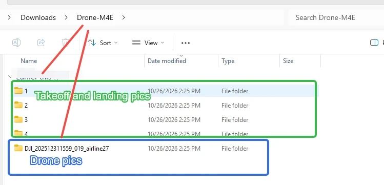
Import the ground data and drone photos in the Aerial-Ground Map Fusion feature
Note: The aerial data must include takeoff and landing data. When importing aerial data, import all photos shot by the drone and additionally select the takeoff-and-landing point photo folder. For a live demonstration of the import workflow, refer to the video tutorial on the official website.
Related Practice
The following is a capture example of a park of about 300 ㎡. The park has distinct overall features, so the diagonals in four directions are used as takeoff and landing points. The ground capture route and takeoff-and-landing point planning are shown in the image below.
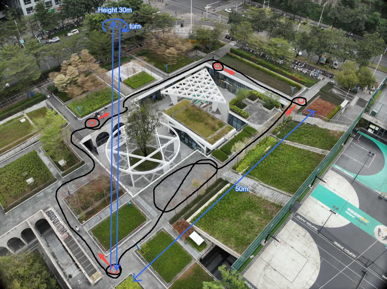
Capture route schematic
Key capture points:
- Takeoff and landing point planning (red points in the image):
- The park has relatively distinct overall features, so the four corners of the park are chosen as the Aerial-Ground Map Fusion points and tie-point orientations.
- This orientation is also the takeoff orientation for the drone's takeoff and landing photos; the two Aerial-Ground Map Fusion points are about 50 m apart.
- Ground capture route (black path in the image; this case uses the P1 as the ground data capture device):
- The walking route follows the outer perimeter of the park to cover the entire capture area.
- At each takeoff and landing point, place an Aerial-Ground Map Fusion point, then orbit once around the location.
- Preview of some aerial photo examples:
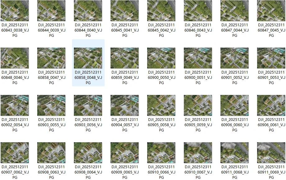
Oblique route photo (smart oblique capture)
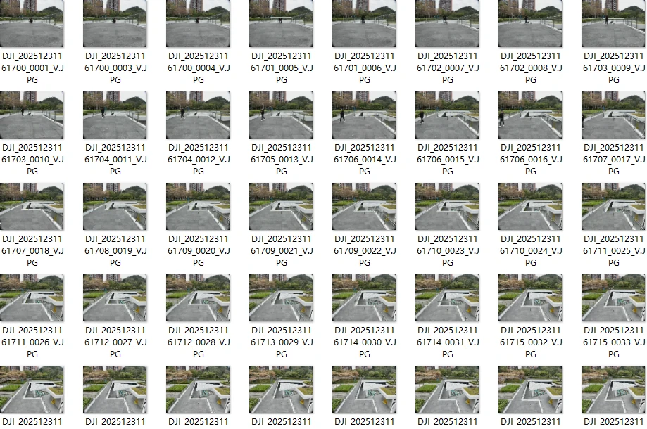
Takeoff and landing point 1
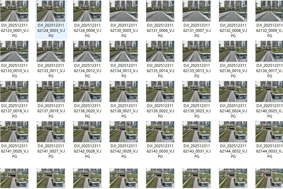
Takeoff and landing point 2
Takeoff and landing point 3
Takeoff and landing point 4
Takeoff and landing shots at each point
- Preview of the model reconstruction result:
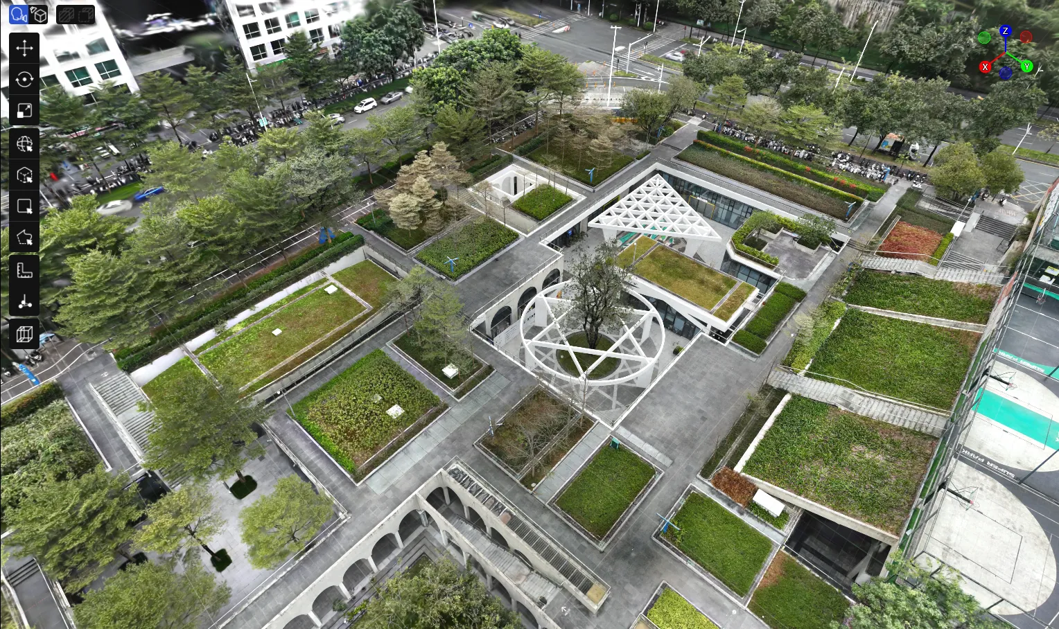
Model result after Aerial-Ground Map Fusion reconstruction